 Device for Dismounting of bearings is shown in figure 13. They are as follows: from the bearing, remove the separator, pushing the balls enter between the collars of the bearing lugs is rotated 90° and in this position zakanchivaut nuts. Screw compress the bearing from the trunnion of the crankshaft. The demolition is over.
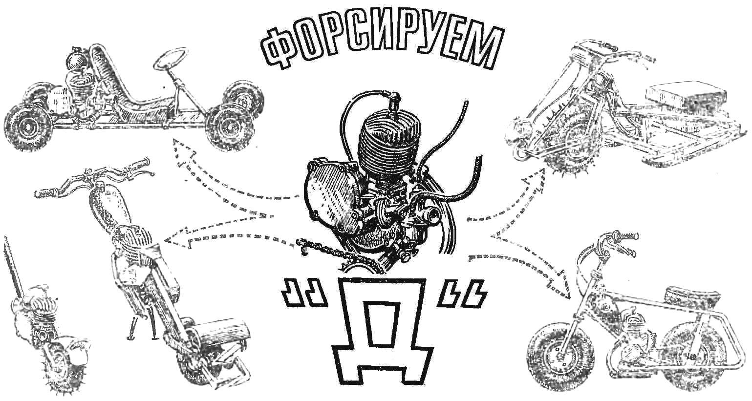
Then proceed to the modernization of the intake system. The inlet channel in the right half of the crankcase unfold cylindrical reamer Ø12 mm and process it from the axle of the crankshaft using a drill or a needle file to square cross-section with a size of 12X12 mm. Next, install the intake phase, corresponding to the diagram above (see Fig. 2). The crankshaft is inserted into the right half of the crankcase without bearing on the right shaft is fastened a circle of thin plywood or sheet metal, on the outer circumference of which a scale in degrees (you can use two school protractor large size). Half of the crankcase strengthen in a vise, using wooden spacers, install the crankshaft position of bottom dead center (BDC), and combine the “0” scale arrow fixedly attached to the crankcase. For convenience, define BDC and TDC is recommended to set the piston in the cylinder, screwed the latter to the right half of the crankcase. Turn crankshaft in direction of engine rotation (counterclockwise when viewed from the side of the right axle] at 40° after BDC, and through the inlet channel applied to the axle shaft risk the lower edge of the inlet channel. The shaft is removed from crankcase and cut the intake window to the risks. The opposite side of the inlet window is partially sealed tin or Triticum or fill with epoxy resin mixed with aluminum powder. Again set the crankshaft in the right half of the crankcase, fasten the graduated disk, as stated above, the crank shaft in the direction of engine rotation to 40° after top dead center (TDC) and make risk on the soldered part of the axle on the upper edge of the inlet channel. Remove the shaft from the housing, cut down the excess solder or epoxy putty.
You can begin to assemble the motor. However, it is recommended to reduce the tightness in the fit of the bearings, pricenew axle crankshaft and a roller clutch to a sliding landing. For this purpose, laps shown in figure 14. (Before final Assembly of the engine be sure to carefully wash the parts in kerosene.)
The first stage of Assembly and installation into the crankcase crankshaft bearing. Half of the crankcase is heated on a hot plate or in an air bath to 70-80°. The degree of heating is determined by the touching details of a match head. Combustible structure should leave a trace, but did not ignite. The bearing are pressed into the heated crankcase half using the mandrel shown in figure 15. Similarly, install the bearing and in the other half of the crankcase. Since the axle of the crankshaft lapped, its installation requires no special tools. Between the two halves of the crankcase put the factory spacer, the crankshaft is inserted into the bearings, tighten all the screws, tightening half of the crankcase. Final fit of pins crankshaft crankshaft bearings is a gradual tightening of these screws. Tighten the crankcase need in sequence and gradually. The tightening procedure is shown in figure 16. Under the screws necessary to put the spring washer.
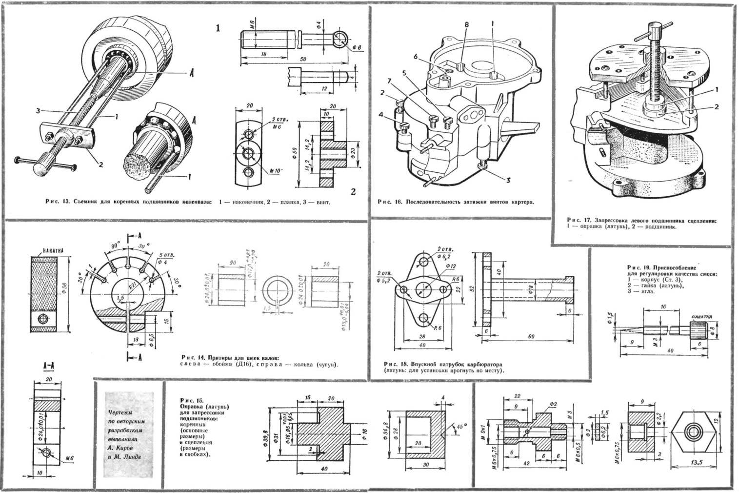
Fig. 13. Puller for crankshaft main bearing:
1 — tip, 2 — strip, 3 — screw.
Fig. 14. Lapping for journals of shafts:
left — clip (D16), right ring (cast iron).
Fig. 15. Bar (brass) for pressing bearings:
indigenous (basic dimensions) and adhesion (dimensions in brackets).
Fig. 16. Torque sequence of the bolts of the crankcase.
Fig. 17. Press the left clutch bearings:
1 — mandrel (brass), 2 — bearing.
Fig. 18. The inlet fitting of the carb
(brass: installation bend in place).
Fig. 19 Device to adjust the quality of a mixture:
1 — housing (Article 3), 2 — nut (brass), 3 — needle.
Then assemble the clutch. Install bearing roller clutch o-ring in the right half of the crankcase. When pressing the bearing using the mandrel shown in figure 15. Insert the roller clutch Assembly with spring resistant nuts and rod, press the left side bearing using universal puller and the mandrel (Fig. 17). I put my left o-ring.
Now put the piston. For this purpose it is heated to 70— 80° C (temperature control, as described above), then use the tools shown in figure 8, press the piston pin (see Fig. 9), but without the mandrel. Oiled, it needs to be in the hole of the upper connecting rod from small presses hand. The gap between the finger and the bosses of the piston to 0.005 mm.
Cylinder set, putting it under the factory gasket. Nuts of fastening of the cylinder tighten diagonally. Using the feeler gauge check the clearance between the piston and the sleeve. It is equal to 0,05—0,07 mm. Lower edge of the inlet ports of the cartridges must match with the top face of the piston in BDC position. This is achieved by installing shims under the cylinder of different thickness. (In the manufacture of linings recommend the use of annealed red copper or sheet aluminum.) Check the absence of bias of the piston. When measuring the clearance left and right of the piston pin, the probe should enter between the sleeve and the piston with the same force. In the case of bias it is necessary to remove the cylinder and installing the connecting rod on the two supports of durable wood, easy blows of a hammer from soft metal to align it. The distortions reduce the power of the engine and cause premature wear of parts.
Further, the Assembly is detailed in the factory manual.
On converted so the motor we recommend to set the carb with a Central float chamber from the boat motor “salute” or from the Cycling motor MAW (trade, Germany) with a cone diameter of 11 mm. the Drawing the inlet for the carb MAW is shown in figure 18. It is also useful to upgrade the carburetor, increasing the hole diameter to 0.9 mm nozzle and needle setting you can adjust the mixture (Fig. 19). Use the muffler from a motorcycle “Java-05”.
The converted engine has a compression ratio of 12-13. Moped full load (own weight of 45 kg, the driver is 85 kg, 15 kg Luggage, only 145 kg) develops on the horizontal sections of the highway speed of 55-60 km/h (with driven sprocket 46 teeth total gear ratio 19, 31 : 1), which corresponds to 8500-9000 rpm it can easily overcome the climbs and freely towing a trailer weighing about 100 kg.
Forced motor requires slightly different adjustments than that specified in factory manual. At a compression ratio of 12.5 — 13 spark advance should be set to 1.2 — 1.6 mm before TDC and apply cold enough candles, for example A US 6.5. As fuel use gasoline AI-93, A-95 in a mixture of aviation oils MS-20 or MK-22 in the ratio of 20: 1.
In conclusion, we must warn you that by force motors of the series “D” as described above, reduces the service life, require frequent adjustments of the ignition, as the details of the factory circuit breaker cannot withstand prolonged operation at 7000-3000 rpm to Start work on the crossing of the motors is possible only with sufficient experience in their operation and made a whole set of special tool, which was mentioned in our article, for disassembly and Assembly of the engine with a hammer lead to very sad consequences.
F. KISELEV
Recommend to read
 MECHANICAL RUFF
Nimble like a river "the namesake" this mechanical brush can penetrate into the most inaccessible places, clearing different channels in the machine parts or equipment. Not necessarily... THE SCREEN-GRID
Offer a convenient way to store lattices for the bathroom. They should be using metal hooks to hang over the edge of the bath in Thane they will not take the place of, and in addition,...
