 The start of the internal combustion engine of a car even in winter, after long-term Parking is often a big problem. To an even greater extent this issue is relevant for heavy duty trucks and automotive technology, many of whom are already in private use — because they are operated mainly in terms of outside storage.
And the reason for a hard start is not always that the battery is “not Prime”. Its capacity depends not only on lifespan but also on the viscosity of the electrolyte, which, as we know, thickens with decreasing temperature. And it tends to slow down chemical reactions with its participation and reduction of battery current in starter mode (about 1% for every degree temperature drop). Thus, even a new battery in winter are significantly loses its launcher capabilities.
To protect yourself from unnecessary troubles related to start vehicle in cold season, I made the starter (PU).
The calculation of its parameters was carried out according to the methods specified in the list of references [1].
Working current of the battery in the starter mode is: IP = 3 x (A),
where C is the nominal battery capacity in A·h.
As you know, the working voltage on each battery (the”Bank”) shall not be below 1.75 In, that is for the battery, consisting of six “cans”, the minimum operating voltage of the battery Up will be 10.5 V.
The power fed to the starter: PCT = Up x Ip (W).
For example, if a passenger car is equipped with rechargeable battery 6 ST-60 (C = 60A (4), the PCT will be 1,890 watts.

Such a starter device can make the tractor in the dead of winter
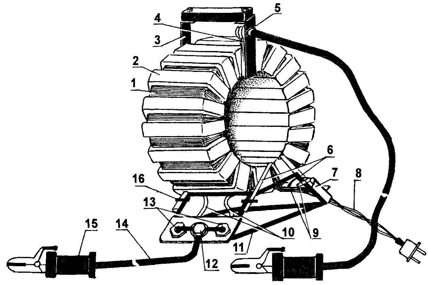
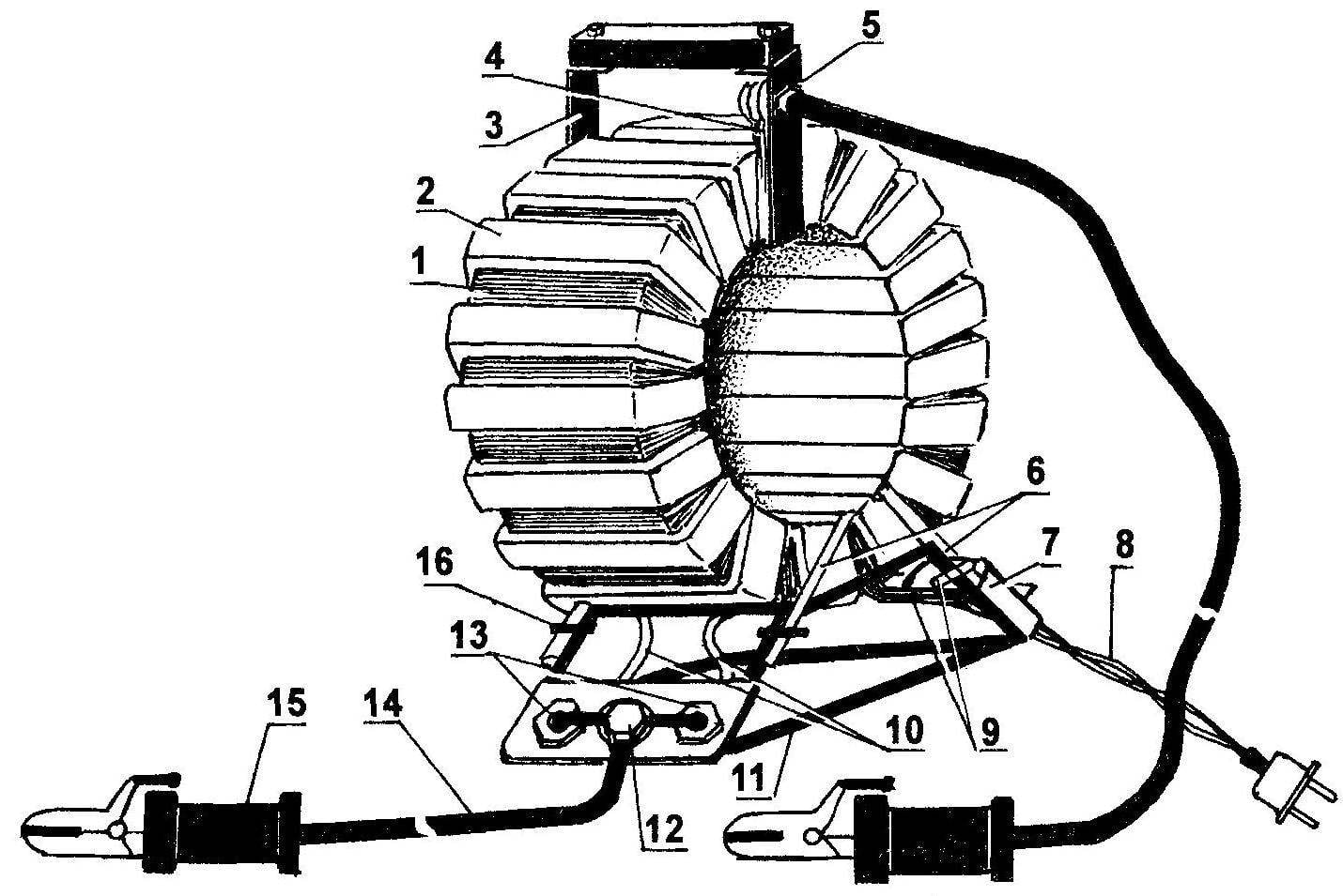
Fig. 1. General view of the starting device with a single-phase transformer:
1 — primary winding (copper wire PETV Ø2. 12); 2 — secondary winding (aluminum tire Sec = 36 mm2); 3 — arm with wooden handle (steel strip 20×3); 4 — the total output of the secondary winding; 5 — zero terminal (bolt M10); 6 — bracket fastenings of the transformer to the base (steel rod Ø7, wrapped with fiberglass impregnated with epoxy resin 2); 7 — mains switch with built-in thermal protection (type AE-1031); 8 — power cord with plug; 9— network entries of the primary winding; 10 — conclusions of the secondary winding; 11 is the base (steel rod 07); 12 — negative terminal (M10); 13 — rectifier diodes (such Д161 — Д250); 14 — lead wire (stranded copper wire 12 in the rubber insulation, 2); 15 — a clamp handle (ticks, 2); 16 connection bracket with the base (a wire twist, 4 PCs.)
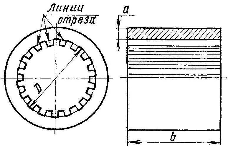
Fig. 2. The magnetic core (toroidal core) — a modified stator of the asynchronous motor (teeth cut in a circle)
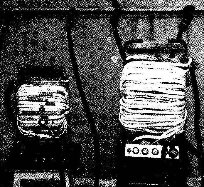
Starting device with toroidal transformers:
on the right is three-phase, left — single-phase
According to this calculation, according to the scheme given in [2], was manufactured of appropriate power.
However, its operation has shown that the call device triggering device was only possible with a certain degree of conditionality. The device was able to work only in the “cigarette lighter”, ie together with the battery of the car. At low outside temperatures start the engine with it, had to be carried out in two stages:
— charging the battery for 10 to 20 seconds;
— joint (battery and device) promotion of the engine.
Acceptable rotational speed of the starter was maintained for 3 to 5 seconds, and then sharply decreased, and if at this time the engine wouldn’t start, had to be repeated all over again, sometimes several times. Such a process not only tedious, but also undesirable for two reasons:
— first, leads to overheating of the starter motor and increased wear;
— second, it reduces the service life of the battery.
It became clear that to avoid these negative effects is possible only when the capacity of the PU will be sufficient for a cold start car engine without using the battery.
Therefore, it was decided to make another device that satisfies a specified requirement. But now the calculation was carried out taking into account the losses in the rectifier unit, lead wires, and even on contact surfaces of joints when possible their oxidation. Also taken into account another circumstance. Operating current in the primary winding of the transformer when starting the engine can reach values of 18 And 20, causing a voltage drop in lead wires of the lighting network for 15 — 20 V. Thus, to the primary winding of the transformer 220 is applied, and only 200 V.
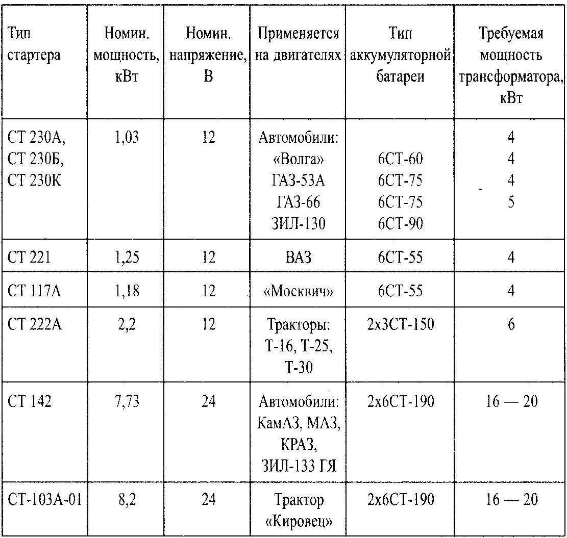
According to a new calculation by the method specified in [3], taking into account all losses of power (about 1.5 kW), for the new PU required a step-down transformer with a capacity of 4 kW, that is almost four times higher than the rated power. (The relevant calculations were produced for the manufacture of such devices designed for starting engines of various machines, such as gasoline and diesel, and even with on-Board network voltage of 24 V. the results are summarized in the table.)
In these capacities provided by the frequency of rotation of the crankshaft (40 — 50 rpm for gasoline engines and 80 — 120 rpm — for diesel), which ensures reliable starting of the engine.
Step-down transformer was manufactured on a toroidal core, taken from the burned-out stator asynchronous motor with power 5 kW. The cross-sectional area of the magnetic St = a x b = 20 x 135 = 2700 (mm2) (see Fig.2).
A few words about the preparation of a toroidal core. The stator of the electric motor freed from residual winding and using a sharpened chisel and hammer knocking out his teeth. This is not difficult, as the iron is soft, but you need to use protective glasses and gloves.
The material and design of the arm and base PU is not critical, as long as they perform their functions. I have the lever is made of steel strip section 20 x 3 mm, with wooden handle. The strip is wound fiberglass and epoxy resin. On arm mounted terminal, which is then connected to the input of the primary winding and the positive lead of the starter.
The base-frame is made of steel rod with a diameter of 7 mm in the form of a truncated pyramid edges of which they are. The device then extends to the base of the two U-shaped brackets, which are also wrapped with fiberglass and epoxy resin.
To one side of the grounds attached a network switch to another copper — plate rectifier unit (two diode). The plate is mounted on the “minus” terminal. Simultaneously, the plate serves as a heat sink.
Switch — type AE-1031, with built-in thermal protection designed for the current 25 A. the Diode — type Д161 —Д250.
The estimated current density in the windings 3 to 5 A/mm2. The number of coils To 1 V operating voltage is calculated according to the formula: T = 30/St. The number of turns of the primary winding of the transformer was as follows: W1 = 220 x T = 220 x 30/27 = 244; secondary winding: W2 = W3 = 16 x T = 16×30/27 = 18.
The primary winding — of the wire PETV with a diameter of 2.12 mm, the secondary — aluminum bus cross-sectional area of 36 mm2.
Was first primary winding is wound with a uniform distribution of coils around the perimeter. Then through the power cord, turn on and measure the idle current, which must not exceed 3.5 A. It must be remembered that even a slight decrease in the number of turns will lead to a substantial increase in the no-load current and, consequently, to decrease of power transformer and PU. The increase in the number of turns is not desirable — it reduces the efficiency of the transformer.
The turns of the secondary winding is evenly distributed around the perimeter of the core. When laying using a wooden hammer. Conclusions are then connected to diodes, and diodes to the negative terminal on the panel. The average total output of the secondary winding is connected to the “positive” terminal, located on the handle.
Now about the wires connecting the starting device with the starter. Any carelessness in their manufacture can negate all the efforts. We show this by a concrete example. Let the resistance Rпр just connecting path from the rectifier to the starter is equal to 0.01 Ohms. Then, when current Ip = 250 A voltage drop on the wires is as follows: IPR = IP x Rпр = 250 A x 0.01 Ω = 2.5; the power losses at the wires is very significant: RPR = IPR x IP = 625 watts.
As a result, the starter in the operating mode will be the voltage 14, and 11.5 V, which is of course undesirable. Therefore, the length of the connecting wires should be as small as possible (Lп < 1.5 m), and the area of the cross section — as much as possible (Sn >100 mm2). Wire is necessary to pick up the stranded copper, rubber insulation. The connection to the starter is quick, powerful pliers or clamps, for example, those used as electrodes holders for home welding machines. In order not to reverse the polarity, stick ticks positive wire wrapped red tape, minus — black.

Fig. 3. A circuit diagram of a starting device with a single-phase transformer
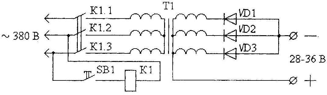
Fig. 4. A circuit diagram of a starting device with three-phase transformer:
SB1 — button switch (type KU-121-1, KU-122-1M) K1 — magnetic contactor (types PML-4000, PMA-4000); VD1, VD2, VD3 rectifier diode types Д161 —Д250; T1 —three-phase transformer 380/36V; K1.1, K1.2, K1.3 — normally-open contacts of a three-pole switch
Short-term mode of operation of the starter (5 to 10 seconds) allows its use in single-phase networks. For more powerful starters (more than 2.5 kW) PU transformer should be three phase.
Simplified calculation of three-phase transformer for its manufacture can be produced according to recommendations in [3], or use a pre-industrial lowering transformers of TSPK — 20 A, TMOB — 63, etc., connected to three-phase network with voltage of 380 V and outstanding secondary voltage of 36 V.
In conclusion, a few General tips and recommendations.
The use of toroidal transformers for single phase starters and not necessarily dictated only their best mass-dimensional indicators (weight about 13 kg). However, the technology of making PU on the basis of their most time-consuming.
Calculation of the transformer of the starting device has some peculiarities. For example, the calculation of the number of turns on 1 In the operating voltage produced by the formula: T = 30/Sct (Sct where the cross — sectional area of the magnetic circuit), is explained by the desire to “squeeze out” of the magnetic maximum to the detriment of the economy. This is justified by its short-term (5 — 10 seconds) mode of operation. If the dimensions do not play a decisive role, it is possible to use more sparing mode, after the calculation according to the formula: T = 35/St. Then take the magnetic cross section by 25 — 30% more.
The required power of transformer starting device, for starters in various cars and tractors
Power that you can pick with made PU, is approximately equal to the power of three-phase asynchronous motor, used in the transformer core.
Using a powerful trigger device in the stationary system according to the requirements of TB must be earthed. Arm coupling gap should be in the rubber insulation. To avoid confusion, the “plus” part of them would want to mark, for example, red tape.
At start-up battery can not be disconnected from the starter. In this case, the mites attach to the corresponding terminals of the battery. To avoid overcharge of the battery, the starter after starting the engine immediately shut off.
S. GUROV, S. Il’inka, Rostov region.
Literature
1. N. M. Ilyin, Yu. l. Timofeev, V. Y. Vanya-s. Electrical equipment of cars. M.: Transport, 1982.
2. I. P. Shelestov. Amateurs useful scheme. Book 1, M.: “Salty”, 1998.
3. I. Nikiforov. Simplified calculation of network of a transformer, “Radio”, 2000, № 10, p.39.
4. V. Motuzas. Electromusic, “Rural mechanic”, 1988, № 4, p. 23-24.
Recommend to read
 SMOKING WITHOUT SMOKE…
No, we are not talking about the latter-day method of processing products using existing industry liquid smoke (to taste qualities of such meats to speak of). For natural smoked... LAUNDRY UNDER THE TAP
With the departure of the old way of life disappear and characteristic things. I think you have forgotten such as a trough or a washing Board. However, the latter remembered...
