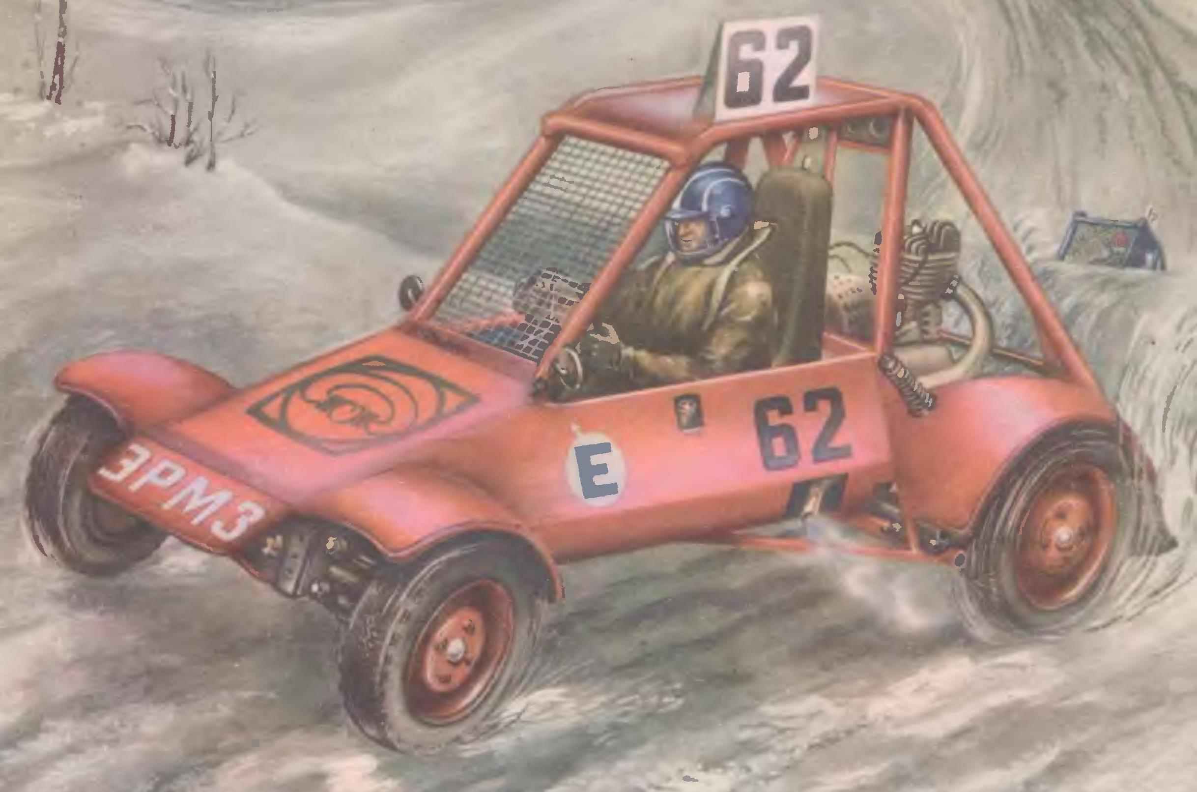
 Every Sunday the gates are opened to the sports section “Buggy ERMZ”. To the factory yard with the characteristic of motorcycle engines crack go dirt buggy. Today exercise. Guys this day is going to the most and everyone wants to try the forces in front of its closest competition, after all, to drive lucky one who has shown the best result of training and worked hard in the creation and preparation of the machine for the contest. The guys mostly 16-20 years, many of them are passionate about technology with 3-5 grade and have Sidney wit. Sports for them is a favorite form of leisure. But soon they will graduate come to the production, army groups, and the technical knowledge and practical sports skills, fitness, purchased in the sports section, will probably come in handy in life. Practice shows that those who engaged in technical sports, proactive and hardworking in the production, they usually say “Jack of all trades”.
 Those who are into designing and manufacturing buggies and going to actively participate in sports, I would like to tell you about the experience of our panel, to give a few tips on where to start, and offer for making a simple design of a cross car.
First of all properly evaluate your capabilities. In Motorsport the most popular buggies with engines from production cars. By intra classification is 7-12 classes special jumper car (SKA) — this is the official nazvanie these machines. For their production requires expensive units, sets zalesnoye parts, as a rule, very scarce. Such resources include the sports section of large enterprises, factories. The young section to compete with them is very difficult.
 Better if you start with “zero” — zero-buggy class. In the manufacture of mini buggy you will learn the work on different machines possess a number of useful skills. Buggies with engine capacity of 350 cm3 and a high school athlete already from the age of 16 will be able to polegate the basics of driving skill, to participate and compete.
Before you start building cars, you need to organize your classes and sections, and the section is primarily collective. It’s hard to work without the necessary equipment, materials and parts, but a bit of a loner, passionate about the same thing, is simply impossible. It is best if the section would exist in the primary organization DOSAAF, sports-technical club, at the center of youth technical creativity, station of young technicians, where, as a rule, the head — qualified, interested in people. It will help to organize a workshop, to find materials and parts DPJ construction machines, as well as clearly define the rights and obligations of each and in the manufacture of machinery and to participate in sports competitions.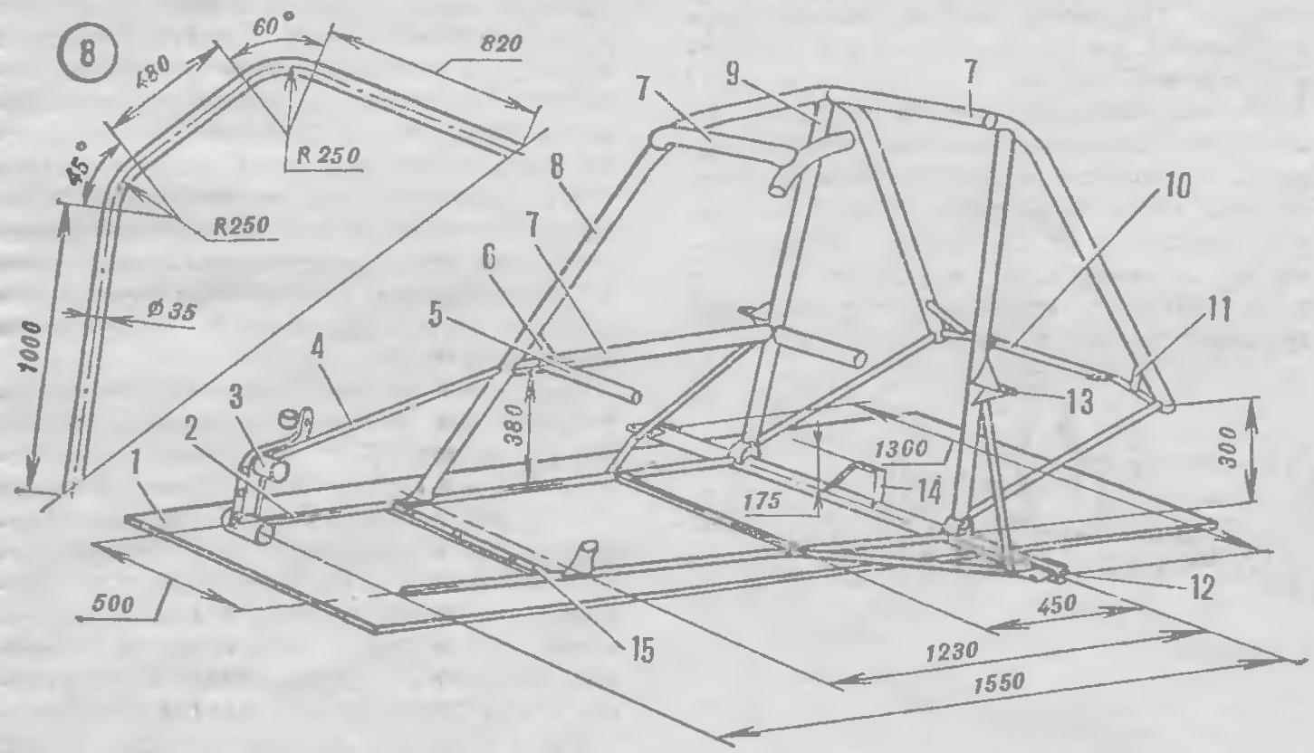
Another very important question — technical support section. Motorsports is among the technically complex sport, so for self-production of machines and keeping them in shape requires a separate room, spacious enough for equipment to there workshop and storage of machinery, materials and parts. The workshop must be equipped with a locksmith workbench with a set of tools, electric hand drill, bench drill, grinding machines, welding apparatus for welding epitropoulos and universalnym lathe.
In spite of maximum use in the design of standard components and assemblies, the frame skeleton of the machine homemade. 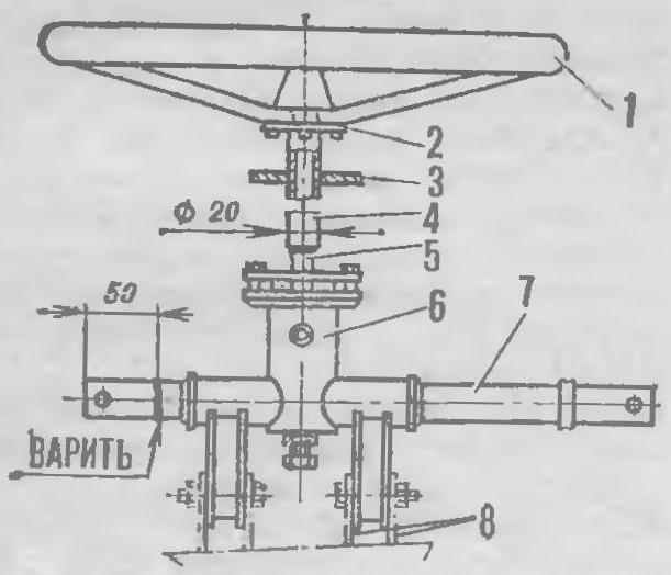 Main load-bearing elements — arc security and cross beam are made of steel pipe ø 35X2. In accordance with the requirements of the Central Committee of DOSAAF to the jumper car set forth in the “Classification and technical requirements to vehicles participating in the competition” (Kitt), it must be cold drawn with a yield strength of at least 45 kg/mm2. Such characteristics have a high alloyed steel 30KHGSA. However, due to the difficulties associated with the removal of residual stresses in the weld, in practice, in the construction of cross car tubes are used conventional structural steels, but somewhat larger cross-section — d 38X2, in addition, they are less scarce. For struts, the struts and frame elements that do not carry significant loads, use pipe-section d 20X2. One car will require about 10 m of such pipes, lines in shorter than 1 m. the Gusset plate, brackets, stiffeners, lugs podsoedenit cut from steel sheet of thickness 2 — 2.5 mm. And the bottom of the machine, partitions the driver’s compartment, decorative panels and wings are made from sheets of aluminum alloys of the D16 type, AMg6 with thickness of 0.6—1.2 mm. On one car will take no more than four sheets of 1200X600 mm.
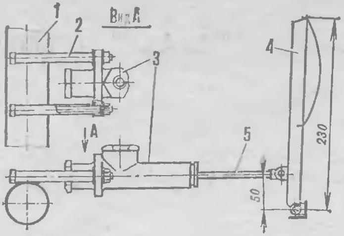
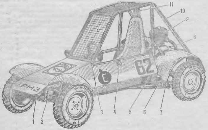
The proposed design of the buggy the zero class is entirely based on units motorized FDD: the engine and subframe Assembly, cupola transmission and axles, front and rear suspension, steering gear, wheels and braking system. Only but the rear suspension uses coil springs and dampers from scooter “Vyatka”.
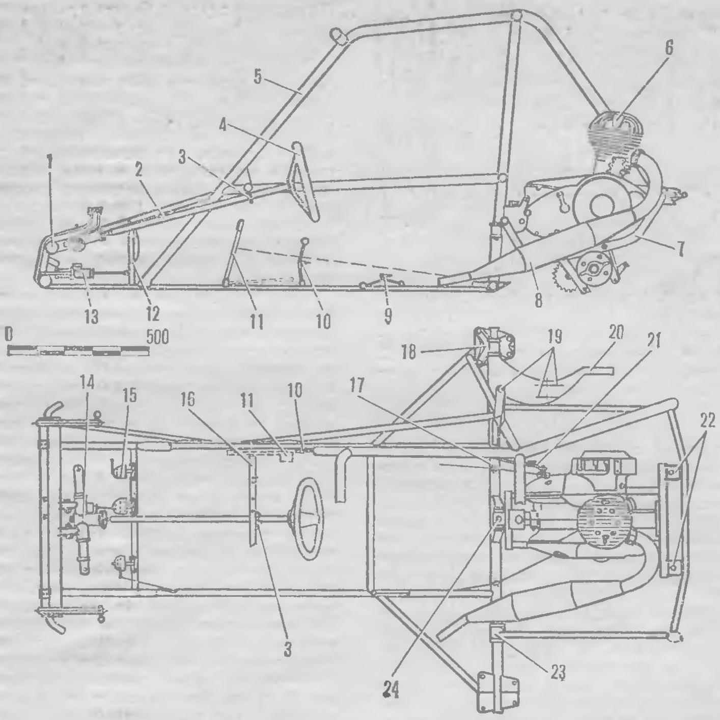
The main bearing element of the structure is frame, welded from tubes. To build Remy and Assembly of the units is necessary to prepare the frame — rectangular table dimensions 2000x 600 mm leg height — 1000 mm. with Paint or chalk on its surface is applied to the drawing of the base frame and life-size and the contours of the mounted components and assemblies. This method allows you to place them most efficiently, avoid trudnosravnimyh layout errors. Then all laid out on the slipway and connect pipes. The brackets and mounting lugs welded to the frame, pre-podsobrav with your site. This eliminates the necessity of carefully marking their position: it is enough to set the node in the selected maete, and then just “grab” bracket to the frame by welding.
 Pipes of a larger cross-section, d or 35X2 38X2 made arc security, installed longitudinally, two uprights, cross beam and the pipe of the driver’s compartment — Daye longitudinal and three transverse. The remaining elements of the frame of the pipe-section d 20X2 mm pipe Joints dovetail with a hacksaw and a file.
Front suspension Assembly welded to the side members of the frame so that it is tilted relative to its former position 12° back. This is achieved by a greater slope snorna that uluchshit maneuverability because of the decline of the wheels to the center of the bend and the removal of the contact patch outside of the rut. Though in this case some increase of effort at the steering wheel, but clearance of the front suspension increases.
In steering gear made small changes. So how buggy it is installed in the plane of symmetry of the machine, the tie rods connected to lugs of the rack on both sides. This eyelet fastening finger of the right thrust cut off and welded on the other side of the rail. Tie rods shorten, cutting their middle part so that after welding, the distance between the centers of steering of the fingers was 400 mm and allow adjustment of their length in both directions. The shaft the steering wheel is welded to the shaft pinion the rack and pinion. On the other end fits over the cut steel plate washer, and then welded to the flange of the steering wheel. Adding to the body of the machine lashing rings, the whole Assembly mounted on the frame. Placing the shaft of the steering wheel, the longitudinal axis of the vehicle to determine the position of the eyelets housing the rack and pinion on the top tube of the front suspension. Plate washer steering shaft serving as an upper support is welded to the middle horizontal struts of the instrument panel. As the helical rail, set its axis parallel to the transverse axis of the machine will fail and, although somewhat altered orientation of the mechanism a bit would violate the geometry of the actuator, to drive the car this noticeable effect will not.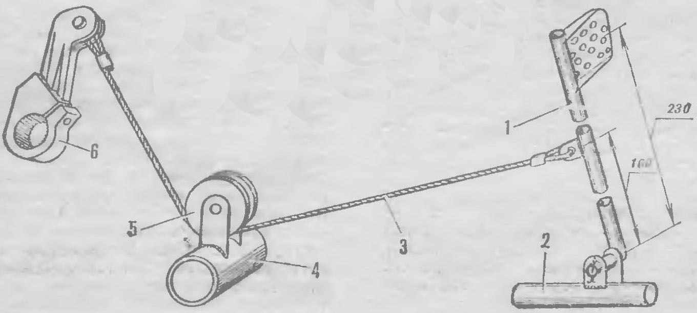
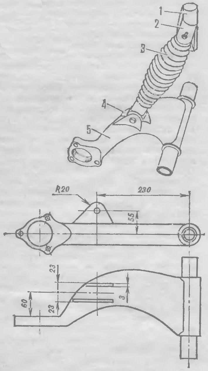
Rear suspension wishbone arms mounted on a transverse tube of the frame through cylindrical hinges. To do this, use the four brackets that are welded internal hinges (on top of the pipe, and screwed to the outside.
For mounting them on the ends of cross pipes are made of plate support. Springs with shock absorbers mounted on the vehicle. The shock absorber going from the upper and lower eyelets, the prepared steel plates. The lower are welded to the arms at a distance of 230 mm from the axis of swing. The wishbone rear suspension is lowered by 20° below the horizontal and the maximum sliding rods of the shock absorbers, determine the position of the upper lug on the rack frame.
The load here will be quite large, so their upper brackets reinforce the gusset.
The subframe power unit mounted on the machine at three points: high, U-shaped bracket in the center of the cross tube and two welded to the rear cross tube of frame. For error-free installation of their weld to the frame at the front, and billet rear Prader-Nita to the subframe. Securing the subassembly in the front bracket and putting it along the longitudinal axis of the machine, determine the place of welding the rear brackets.
Great importance for the success of the competition has the rational layout of the controls. From motorized uses only the levers of the shifter and turning on the reverse with their rods. Three self-made pedal with cable-drive clutch and the throttle of the carburetor is mounted on the transverse area voditelskogo Polycom office. Brake master cylinder is attached with welded horizontal tubes on the tube front axle, so the pedal acts on the piston of his direct stock. To start the engine from the driver’s seat installed mechanical kick-starter cable-drive from the optional footswitch. Her bracket is welded to the right side member of the frame. Thanks foot the engine is started the construction of the machine became much easier. With the engine removed not only the starter and generator. The DPJ and the necessary ignition system, brake lights and horn power supply provides a small battery. It is also harvested from an old car. For this loading plug is determined by three banks and the most capacious of them are lightweight the battery is 6 V.
