M-K “.
As a result, I accumulated some experience of designing and has already planned not as a child, and “adult” car. Called it “mouse-2”. Built a long time, or rather, not so much built, how many were looking for the necessary parts. This, in particular, due to the use of “Mouse-2” mechanical brakes (now I change them for hydraulic). Development drawings and the construction was carried out simultaneously, although the basic parameters of the “Mouse-2” was thought out by me in advance.
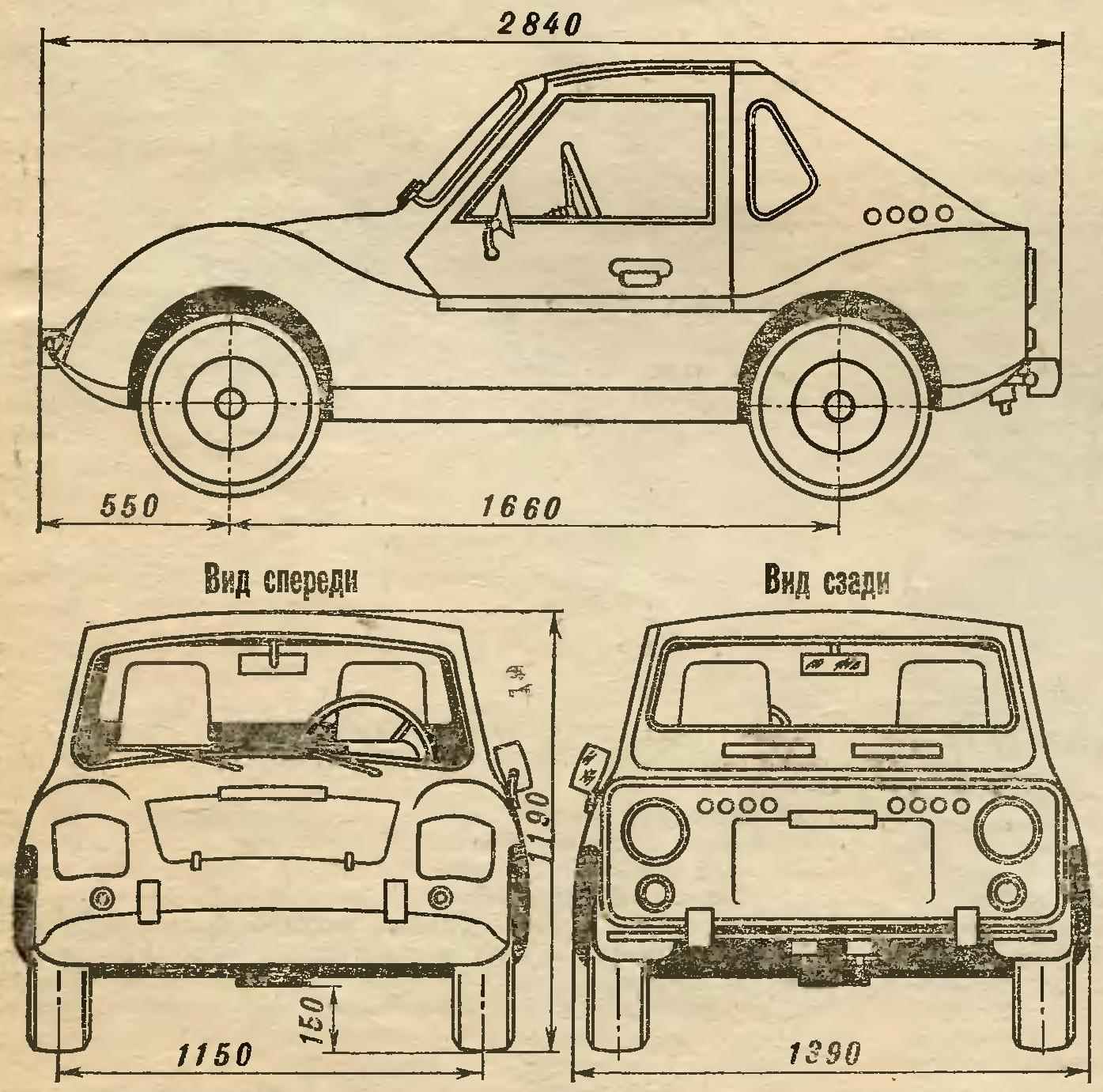
Bring him brief technical description. This twin four wheeled vehicle with an engine producing 14 HP (working volume of 346 cm3) located in the back. Equipped with two independent braking systems: a primary (working) foot all-wheel drive and a spare (side) lever actuated on the rear wheels only.
The car is dynamic and stable. The braking distance at a speed of 30 km/h not more than 6.5 m minimum turning radius along the axis of the track the outside wheels — 4.5 m. the Maximum speed of 65 km/h.
Electrical equipment, from motorized wheelchairs FDD, 12-volt, slightly modified. It includes exterior lights and light-signalling devices, horn wiper, instrumentation.
Salon decorated with modern materials, isolated from matousek sound absorbing panel with foam filler. Chairs, driver and passenger anatomic, laminated of fiberglass, lined with foam and covered with leatherette; the machine is equipped with safety belts.
The vehicle is operated from may 1985. The speedometer is many thousands of kilometers of the Sakhalin roads. Serious breakdowns in the way it was. However, it should be noted that, if full engine power is not enough to overcome frequently encountered on our roads are steep and long ascents. And it forces to include the first transfer. Critical of I also to a flip-up doors — not all they are comfortable. Otherwise, the machine is happy.
Now I would like to tell you about the design features “Mouse-2”.
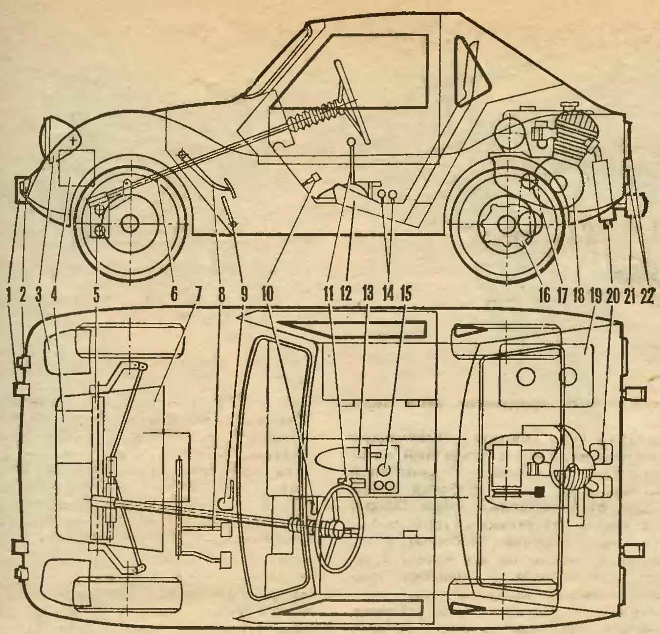
Fig. 2. The layout of the car:
1 — the front buffers,
2 — sidelights — direction indicators,
3 — retractable headlights with covers,
4 — battery,
5 — front axle,
6 — steering shaft,
7 — the Luggage compartment,
8 — brake pedal and clutch
9 — the gas pedal,
10 — grip hand brake
11 — shift lever and the reverse
12 — the driver’s seat,
13 — lift headlights,
14 — “coins” of the decompressor and the corrector,
15 — valve fuel cock,
16 — differential with reverse gearbox
17 — drive chain,
18 — engine,
19 — fuel tank,
20 — the silencers,
21 — back buffer,
22 — rear lights.
It is assembled mostly from spare parts of “Zaporozhets” and sidecars, SZA and SZD. Body frame, with fiberglass panels on a tubular basis. Rear hood, hinged or removable, which provides easy access to the engine. Body – the most difficult part, Assembly and equipment spent three-quarters of the time.
First I made a mock body in natural size. I used pure gypsum. To save put on the grid first concrete, and when he grappled caused the top layer of plaster thickness of 15-20 cm Completely dry surface layout, polished and painted by nitroenamel. The treatment was conducted very carefully, so that the flaws are not passed on matrix.
Then spaced lines of connector panels. So they clearly imprinted on the matrix, show them with an awl to a depth of approximately 1 mm thereon and fitted the finished panel.
Usually the matrix is made from fiberglass. But I had to save resin and fiberglass, and had to cast them as the layout of plaster and concrete.
Fig. 3. Typical scheme of dock panels:
1 — tube frame,
2 — wooden rake insert with a groove,
3 — fiberglass lining,
4 — sealing of the joint of the panels with fiberglass,
5 — panel
6 — screw.
Horseflies of each panel was shot separately: rubbed surface of the layout with a thin layer of vaseline or grease and washed down with plaster, overlapping the parting lines at 10-11 mm, and then the concrete by reinforcing it with steel bars 0 5 mm. To obtain casts from the vertical surfaces did the formwork boards and plywood.
After drying of the concrete (approximately three days) removed the matrix doseusual plaster layer, carefully treated and painted.
Main load-bearing panel villeval of six layers of fiberglass with lining of two layers of stalloreggi, which gave a thickness of about 4 mm. Fiberglass before it burned a flame soldering of the pampas, to better absorb resin. Annealed with great care, as the burned spots in the fabric crumbles.
Due to the fact that the glue hardens quickly, had to cook it in small portions, Composition: epoxy resin (100 cm3), plasticizer (10 cm3) and hardener (10 cm3). You can do without plasticizer. If the resin is too thick, it is allowed to add it in acetone or solvent No. 646 or 648 (no more than 10% of the total). However, given that such supplements reduce the strength of the product, use them in a pinch.
To obtain the desired colorant in a resin is injected dye — ordinary artists oil paint from a tube (before the addition of hardener).
Fig.5. The basic power elements of the body:
1 — the front buffers,
2 — front axle (steering gear and suspension arms not shown)
3 —the frame of the car
4 — trim of the Luggage compartment,
5 — front support frame body,
6 — tubes of the core,
7 — lower support of the core,
8 — rod door
9 — the door frame
10 — hinges of doors,
11 — rear support frame,
12 — the frame of the hood,
13 — the hinges of the bonnet,
14 — rear bumper.
Before Villenoy panels I cut out the fiberglass layers with a knife on the plywood sheet (linoleum) and put the pieces in a pile. Glued at one time with short breaks to rest or for the production of a new portion.
After laying in the matrix of the last layer of fiberglass covered everything with plastic wrap and making the formwork, and covered the surface with sand. A day removed sand and press left panel to “ripen” in the matrix three more days. Fully resin polymerized for the week.
The opening for the windshield in the front panel I customized to fit the frame of two-millimeter aluminum sheet, Then this frame is glued into the panel and it is inserted into the front glass of the car ZAZ-968. In the same way was made the rear and glazed panel.
Fig. 8. The engine on the underframe:
1 — engine,
2 — adjusting screw,
3 — adapter
4 — front bracket engine mounts,
5 — under engine frame,
6 — traction suspension differential
7 — differential with reverse gearbox
8 — cover the pan,
9 — rear bracket, engine mounts,
10 — plate sample exhaust
11 — the left silencer.
The finished panel I cut the parting lines on the layout of the body and customized to the tubular frame. Panel to it was fastened with screws, choosing the gaps of the wooden slats with grooves and podkladyvaya them inside 4-6 layers of fiberglass. The joints between the panels were carved steps and was filled with strips of fiberglass on the glue.
The assembled body is finally plastered to the polished, ready for painting. Irregularities were sealed with putty on the basis of the same epoxy glue by adding fillers: talc, aluminum powder and the like.
Fig. 6. The skeleton of the body:
1 — front support,
2 — lower support,
3 — back support
4 — support tubes.
The skeleton of the body is assembled from thin-walled steel pipes, they are welded attachment points to the frame of vehicle: front, bottom and back support.
Tubular design has the frame of the folding hood. If necessary, the latter can generally be removed, for example in the repair of the engine.
The main power element of the body — a rigid frame of steel pipes and corners. She carries a skeleton, hood, front axle, engine, sub frame and differential, chassis, rear wheels, trunk and so on. For mounting these units the fixing brackets, nodes and supports.
Fig. 7. Frame vehicle:
1 — mounting brackets of front axle,
2 — mounting bracket of the shift lever and the reverse
3 — support the passenger seat,
4 — side nodes podstanovki the core of the body,
5 — loop fasteners seat passenger
6 — support pillows sub-frame,
7 — towing fork,
8 — pin bonnet
9 — angles 40 X 40 mm,
10 — the attachment points of the rear suspension wheels.
The front frame is mounted the axle of the sidecar, SZA, has been modified for drum brakes from a cargo scooter.
On the rear of the frame on a makeshift rubber pads mounted under engine frame with the power plant from motorized FDD is deployed to 180°. Its front fork mount adapter, offset vertically relative to the mounting bracket of the engine. Rear point — hinged: bracket, covering the collar of the tube sub-frame, allows a small rotation of the power unit in a vertical plane. It was made for tensioning the drive chain adjusting screw, which, being wrung out from the supporting pad front bracket, lift the engine. Fixation of the degree of tension of the chain is the collar and tie-rods (see Fig. 9 and Fig. 10).
Fig. 9. Sub frame:
1 — front bracket engine mounts,
2 — longitudinal spars,
3 — transverse spars,
4 — cover the pan,
5, 6 — traction suspension differential
7 — cheeks rear bracket engine mounts,
8 — tie rods,
9 — holes for stud mount differential,
10 — stiffener,
11 — the pipe under the clamp back bracket,
12 — clamp.
The torque is transmitted single-row roller goal step 15,875 mm differential with reverse gear from a cargo scooter. The differential is suspended on four studs under the engine on rods and sub-frame. In principle it differs little from motocoaster — the same compact and reliable. However, to obtain the desired number of revolutions of the wheels had to make a new sprocket with 16 teeth.
Transmission, as is known, is built directly into the engine, and reverse — differential. To manage them you must have two levers with the separate drive. I used a single drive switching gear, and reverse, which is much simplified control of the car.
Fig. 10. The installation of the adapter:
1 — front bracket engine mounts,
2 adapter,
3 — adjusting screw,
4 — adjusting hole,
5 — pinch snips.
The shifter in the cab is pivotally mounted between the two gear and reverse and is constantly pressed by a spring to the first. In the neutral position the sectors of the fixed balls, which under the action of its springs are in the grooves of the discs.
For reversing sector gear to translate the lever forward — include the first transfer. Then the lever returns to the neutral position (transmission in this case does not turn off) m again, but with a sector of the reverse, forward serves, including reverse.
Fig. 11. The shift lever and reverse:
1 — the lever
2 — casing,
3 — the sector gear with the drive
4 — sector reverse,
5 — pressure plate,
6 — finger
7 — area of the vehicle frame,
8 — fork thrust reverse,
9 — plug the shift rod,
10 — a bracket of fastening of the lever,
11 — plug,
12 — locking spring,
13 — a ball retainer,
14 — pull the gear shift.
Other engine controls — gas pedal, clutch and the ignition switch is usual, regular.
The layout of the power plant, Matousec dictated and replacing one of the factory muffler on a homemade two — the first did not fit in the hood space.
Fig. 12. Rear suspension:
1 — power train,
2 — the frame of the car
3 — arm suspension,
4 — mount,
5 — pad,
6 — wheel hub,
7 — eyelet fastening arm,
8 — sleeve,
9 — rubber liners,
10 — finger
11 — the case of the lower attachment of the shock absorber,
12 — the edge
13 — eyes of the upper attachment of the shock absorber,
14 — Klondike solitaire.
Mufflers welded from sheet steel. Connect them to the exhaust ports of the cylinders (swivel nuts), and to the mounting bracket of the engine
(insert sample]. It should be noted that the exhaust sound from homemade silencers louder than factory. Probably the impact of their small internal volume. However, engine power is not affected.
Fig. 13. Mufflers:
1 — pinch bolt,
2 clamp,
3 — the casing of the muffler,
4 —transfer tube,
5 — Union nut,
6 — plate attachment to rear mounting bracket engine
7 — ejector,
8 — perforated pipe,
9 — bottom,
10 — the exhaust pipe.
Rear axle assembled from two homemade independent suspension with longitudinal swing arms. The levers of thick-walled steel tubing 32 mm 0 I installed bearings in the ears — the points of fastening to the vehicle frame.
To the opposite ends of the arms welded to the hub of the rear wheels and lower the attachment points of the shock absorbers, which is a cylindrical body with an axial bushings under the bolts and rubber inserts.
Fig. 14. Modified shock:
1 — absorber of a motorcycle “Ural”,
2 — plates under the additional spring
3 — rubber buffer,
4 — spring shock absorber,
5 — additional spring
6 — biscuit.
The upper mounts of shock absorbers is the tabs on the gussets, are welded to the tubular elements of the frame of the car.
Hub and axle of the rear wheels from a cargo scooter; rim and brake components from motorized FDD In a single unit they are connected to the flanges and disks.
Fig. 15. Hub rear wheel:
1 — driveshaft with u-joint,
2 — axle hubs
3 — hub body,
4 — roller bearing,
5 — flange of the brake shield
6 — wheel disk and brake drum,
7 — segment dowel,
8 — a nut of fastening of a disk,
9 — the inner rim,
10 — brake drum,
11 — the outer rim
12 — brake pad,
13 — brake shield.
Rear axle “Mouse-2” is heavily loaded, and the elasticity of the shock absorbers of the motorcycle “Ural”, as it turned out, insufficient. So they had to modify to install additional springs that I made from one of the rear spring of the car ZAZ-968, cutting her gas burner. Sheared edges while they were hot, buckled, and then grind on the grinder for a precise fit in the dish.
Fig. 16. The front wheel hub:
1 — roller bearing,
2 — oil seal,
3 — knuckle,
4— additional flange,
5 — bolt brake shield
6 — hub,
7 — brake his shield
8 — brake pad,
9 — brake drum,
10 — pinch bolt,
11, 12 rims wheels
13 — ring-spacer.
The more complex the alteration the shock absorbers were not exposed. I removed only the outer covers. And dirt from falling on the rods, used protective covers made of thin canvas.
Fig. 17. The layout of the actuator retractable headlamp:
1 — bearing,
2 — the housing axis,
3 — lamp housing,
4 — screw fixing shelves,
5 — the cable of the speedometer,
6 — arm drive,
7 — pull,
8 — the lever
9 — bearing housing shaft,
10 — spacer sleeve with the shaft,
11 — gearbox housing,
12 — panel mount lights,
13 — Farah.
Fig. 18. The drive mechanism of the headlights:
1 — arm,
2 — flywheel,
3 — housing turntable,
4 — the rope of speedometer,
5 — cable sheath,
6 — worm shaft,
7 — worm wheel,
8 — gearbox housing,
9 — lock lever
10 — lever
11 — the bearing housing of the shaft,
12 — shaft,
13 — spacer.
Power axles with cardan joints — also from a cargo scooter. But since the track “Mouse” wider, then they had to be lengthened. The axle shaft I cut in half and pressed in a steel sleeve. The length and fit them in place, welded to each other.
Front wheel is assembled from parts chassis sidecars, SZA and SZD. To connect them together I machined the extra flanges and rings-top box. Of suspension components (except hubs) were not modified. A hub only grind in three places as shown in the figure.
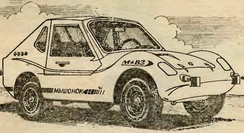
A curious element of my car can be considered retractable headlights. Such are sometimes found in improvised structures. In the afternoon, when there is enough light, hid headlight in the engine compartment, in the evening time they push out.
The lights I have with manual transmission (eventually it will be replaced by electric) installed in the cockpit. From the turntable to a worm reducer with a gear ratio of 1 : 80 stretches the cable of the speedometer in the shell. Further, from a worm wheel gear rotating the shaft, hidden in the spacer sleeve, through the levers and the thrust is transferred to the housings of the headlights, and they are put forward. They are governed by the offset shelves, which are fixed then the side screws.
Recommend to read JET “ALBATROSS” Czechoslovakia justly called the center of Europe: at its plants at different times was created by the machines and equipment are well known throughout the world and is characterized by... SHOE COMBINE Four boards and four brushes is all that is required in order to in the hall of the rural house or cottage has a very convenient fixture for shoes. Thanks to him, easy to remove even...
Scroll back to top
 The first little micro-car “mouse” I built for my kids. As far as he was able, the readers of “Modeller-designer” can tell, after reading his description and drawings, published in “M-K“.