SCOOTER SNOWY EXPANSES

SCOOTER SNOWY EXPANSES

For open snow-covered expanses, in my opinion, there is no better vehicle than a snowmobile. No other ATV can not be compared with them in speed and terrain. Noise really much. But what a fun rapid slide through the untouched virgin snow! Snowmobile, nicknamed “Otter” including the, shall we say, ducking and diving — at the speed they can, even through the sparse bushes “pronanut,” I built in one breath: so very recently I wanted to have a car like that. And so the design of it is thought out thoroughly, and the required units, units and materials prepared in advance.

Snowmobile structurally composed of a boat-ski open single cabin in the Central part. The cabin is extremely simple: it contains only the driver’s seat, controls and Luggage rack. From the incoming air stream of the driver protects the fairing with the windscreen.

Behind the cabin, at the stern of the sled, installed the engine frame, to which is suspended the gasoline engine cooling air power 18 HP with a propeller diameter of 1200 mm. ibid., aft, located on the sides of the two aerodynamic keel, while providing the protection of a zone of rotation of the propeller.

The body of the snowmobile consists of a boat, variable deadrise. All of its law enforcement elements, 11 frames, longitudinal stringers, beams and paneling — made of wood. Instead of a keel boat throughout the length of the ski has, which is to reduce the resistance tapers from the nose to the transom from 300 to 270 mm of the Toe of her bent at the radius of 1000 mm Beyond the bottoms down ski performs at 50 mm, and the frame from No. 7 to the transom of the boat rises gradually to 20 mm. across the sole of the ski and the bottom of the snowmobile slightly convex. The deadrise of the hull at the transom is 11° with a gradual increase up to 24° at midship.

Frames made from plywood brand of BS with a thickness of 10 mm. All of them, except the transom, lightweight cutouts. The frames No. 3 and 8 are the partitions that separate the cabin from the fore and aft compartments. Cabin width is selected such that its side firmly fixed in the driver seat. The soles of his feet rest on the frame № 4, which provides additional convenience in the management of the snowmobile.

 
Aerosan
Aerosan “Otter” (on the top view the engine is not shown)
 
The layout of the snowmobile
The layout of the snowmobile:
 
1 — body; 2 — deflector; 3 — a Luggage shelf; 4 — wind visor; 5,8 — fixed right panel of the cab; 6 — right handle of the control rate (with the lever “gas” and “stop” button motor); 7 — removable right panel of the cabin; 9 — driver’s seat; 10 — right control wiring course; 11 — right keel; 12 — right-brace; 13 — propeller (d1200); 14 is a motor frame; 15 — fuel tank; 16 — left stringer under the engine frame; 17 — transom; 18 — the left axis rudder; 19 — left rudder; 20 — left wedge-skate; 21,24 — frames, partitions; 22 — plate rack left lever rate; 23 — cabin floor; 25 — foam filler; 26 — eye
 
Theoretical drawing spanguoliu
The theoretical drawing spanguoliu
 
The basic power set of the body of the snowmobile
Main power set of the body of the snowmobile:

1 — bow fender (pine, bar 50×30); 2,20— knice (pine, 6 PCs); 3 — side fender (pine, bar 50×30, 2); 4— nasal Carling (pine, rake 50x 15); 5,6 — deck stringers (pine, rail 30×10-4 pieces); 7 — stringer under engine frame (pine, bar 70×20,2); 8 — strengthening the stringers (pine, rail 20×10, 4 PCs.); 9—BIMS attachment of the keel (pine, whetstone 80×70, 2); 10 — feed the Carling (pine, rail 30×10); 11-13 — bottom stringers (pine, rail 30×10, 6 PCs); 14 — stringer skiing (pine, battens 50×50, 2); 15 — Kiel (pine, rail 50×15); 16 insert (Styrofoam, 10 PC); 17 — front bulkhead No. 5 (plywood BS, s10, 11). 18 — Bush under the shaft of the control knob with a course (45 steel, pipe 16×2, L40, 2); 19 — cover plate of the rack control lever course (pine, rail 30×30, 4 pieces); 21 — spacer (steel 45, d36x16x2, 2); 22 — transom (plywood BS, 10); 23,25 — boss (pine, 4x); 24 — wedge-skate (plywood BS, s16, 2 PCs.)

 
Additional fastening of stringers
Additional fastening of the stringers:

A — drilling holes in the stringer and the bulkhead; B — formation of the first twisting and the tension of the wire; — the formation of the second strand; 1 — frame; 2 — stringer; 3 — wire OVS d1,2; 4 — ready mount

 
Nose cone
Nose cone:

1 — boss (pine); 2 — shell spinner (aluminum, sheet s1,5); 3 — wind visor (organic glass, sheet s4); 4 — the roof of the Luggage compartment (aluminum, sheet s1,5); 5 — bolt M4 (9 items); 6 — frame (pine, rail 20×20); 7 — trunk shelf (plywood s3); 8 — strip (wire OVS d2); 9 — screw 6×16

 
All spacey skiing from frame No. 1 to the transom glued in blocks 50 mm thick foam PS-1. On top of the blocks to the frame No. 3 at No. 8 glued floor made of 3 mm plywood. The same material covered and the cabin. Moreover, the left and right part of the skin of the sides made in the form of removable panels for maintenance of the nodes of the control levers. The deck and the bottom is sheathed with plywood, 3 mm thick, the sole of the ski — plywood brand of BS with a thickness of 5 mm.
 
Stands frame № 5 pine reinforced overlays at the locations of the bushings under the shafts of the control levers. The lower part of the lateral branches of this frame separated from the uprights shorter to not interfere with the movement of tail feathers fry, and strengthened by bosses, and glued to the bottom stringers.

At the rear of the case has reinforced stringers that serve for mounting the motor frame and rocking control, as well as the beams (they are glued to the hull, RUB rails) for attaching aerodynamic fins, a wedge-blades and rudders. The deck and bottom stringers at the intersections with the frames additionally fastened with wire loops.


Wedge-skates made from 16 mm plywood brand of BS and are arranged strictly parallel to the longitudinal axis of the body of the snowmobile. The beams they glued spines. Wedge-skates reinforced bosses that make smooth their transition to body and trim, stainless steel (installed after full preparation of the case).

The surface is completely assembled and sheathed with plywood hull covered with putty, smoothed and thoroughly cleansed. Then covered with one layer of fiberglass stamps AST(b). Ski black stainless steel sheet with a thickness of 0.5 mm and bottom sheet of polyethylene.

 
A method of manufacturing a windshield visor
A method of manufacturing a windshield visor:

1 — blank visor (sheet organic glass); 2,4 — clamp; 3 — blowtorch; 5 — model (pine, plywood); 6 — the cutting line of the workpiece
 

Keel
Keel:

1 —root rib (plywood BS, s20); 2—the leading edge (pine, rack 40×25); 3 — boss (pine, 5 PCs); 4 — filler (foam PS-1); 5 — rib (plywood s, 2); 6 — sheathing (plywood s3); 7 — longitudinal (pine, rail 25×25); 8 — d6 hole for the mounting bolt of the strut; 9— ending (pine, rack 40×25); 10 — trailing edge (pine, rack 40×25)

 
Mount Kiel
The attachment of the keel:

1 Kil; 2 — BIMS; 3 — M6 bolt (2 PCs); 4 — 3×20 screws (4 PCs); 5 — weld the bolt head (45 steel, sheet 30×30, s2,2); 6 — puck 20x6x2 (2); 7 — nut M6 (2 PCs.)

 
The basic elements of transaction control
The basic elements of transaction control (right branch):
 
1 — control lever; 2,6 — Pitman; 3, long thrust; 4 — rocking chair; 5 — short pull
 
Knot design right arm upravlinnia
Knot design right arm UPRAVLINNYA:

1 — finger d6 (45 steel); 2 — sleeve under arm shaft (45 steel, pipe 16×2, L40); 3 — wedge (from a carriage of a Bicycle “Eaglet”); 4— a Pitman arm (connecting rod from the carriage of a Bicycle “Eaglet”); 5 — the control lever (steel pipe 22×2); 6—tie rod (steel tube 16×1,5, L1325); 7 — shaft (steel 45, rod d12); 8 — clamp lever (steel 45); 9 — tie rod end (steel 45)

 
Knot design rocking control
Knot design rocking control:

1 — rocking chair (steel 45); 2 — bearing 60201; 3,7 — washer 20x12x2; 4 — M8 castle nut 5 — cotter pin; 6 — axis-pin M8 (wire d12); 8 — 3×6 screws; 9— mortgage nut M8; 10 — deck reinforced stringer

 
Setting ring
The installation of the eye:

1 — ring nut M6; 2 — bow rubbing strake; 3,6 — lock nuts M6, 4 — M6 stud; 5 — frame № 1

 
On the sides attached to the ski by screws with countersunk heads two podraza of steel U10A. The exact position of the undercut I picked up experimentally, moving them to the nose or the rear of the snowmobile (the picture shows a few cage nuts). The sole of the ski down the undercuts are at 12 mm, however, as the feathers of the rudders. This ensures excellent control of the snowmobile on the ice, the crust and Packed snow road.

FAIRING wykroczen from aluminium sheet 1.5 mm thick. Power frames it has. The rear edge of the shell and lid are reinforced rolled them wire grade optical fiber with a diameter of 2 mm. To the body of the snowmobile cowl is attached with screws with round heads through the frame from bruskov by section 20×20 mm, pre-mounted on the deck over the hull. The volume under the cone is used for small packages and medical kits.

WIND VISOR — made of organic glass thickness of 4 mm. way to give the glass the desired shape is clear from the attached drawing. The fairing visor bolted together with M4 boot lid.

The finished hull with a fairing in order to safety nitroglycerene covered with bright colors of yellow and red.

The driver’s SEAT easily removable, allows access to the tool box behind the backrest. Molded seat foam PS-1 and fiberglass AST(b) epoxy resin ED-5. Top covered with leatherette. Fixed projections of the frame № 7 within the recesses of the seat.

AERODYNAMIC KEELS installed on the sides of the stern of the hull. Each keel has a frame consisting of front and rear edges, endings, three ribs and spar. For greater strength internal cavity of the frame filled with blocks of foam PS-1, and the frame sheathed with plywood of 3 mm thickness and painted: yellow background — red stripes. Attached with two M6 bolts to the beams (bottom) and one M6 — brace (top). In the skin of fins above the root ribs made the cut: under front attaching bolts (on inner surface) and a bipod rudders (through). In these places removed of course, and the filler — foam.

The PROPELLER — pusher, laminated (birch slats). Manufactured according to the drawings published in the journal “modelist-Konstruktor” No. 1 in 1975, with a slight change of pace in the direction of increase. Screw painted red. On the tips of the blades with black paint depicts the piping and the parallel strip.

STEERING. Management system course snowmobiles consists of two parallel, symmetric, and independent from other branches — right and left. Each branch has the same set of elements: a lever with rubber handle, shaft, two arm, two rods, rocking and steering the pen.

 
Levers — steel pipe with a diameter 22×2 mm From the rubber grips they are slightly flattened for greater rigidity. By their ends welded split clamps with slotted holes, tighten the steering shaft bolts.

Steering shafts in steel bushings glued, as already mentioned, the racks bulkhead No. 5 and Packed before Assembly lubricant “Litol-24”.

On the other side from the levers on shafts mounted steering arms (rods from carriage baby bike “Eaglet”) and scontrini Cycling wedges. The ends of the bipod is pivotally connected with plugs of long rods by means of steel hardened and splintered fingers. The other end of a rod pivotally connected with the inner shoulders rocking, rotating enclosed and lubricated bearings 60201.

The axis of the stud rockers rigidly mounted on the reinforcements of the deck stringers. On the axes of rocking fixed castellated nuts with cotter pins. External shoulders rocking hinge are connected with short rods that are attached to the bipod. The lower ends of the shafts of the rudders are included in the heel trim wedge-skates. To the shafts of the rudders welded tail feathers of steel grade U10A, reinforced with two strips of the same steel.

Shafts rudders rotates in steel bushings glued in the beams. In addition, the mounts have brackets with which it is additionally fastened to the body of the snowmobile rear mounting bolts of the aerodynamic fins.

 
Steering gear napravlenia
Steering gear napravlena (left branch):

1 — long tie rod (steel tube 16×1,5, L1325); 2 — dust cover (tarpaulin, rod slides freely); 3 — rocker; 4 — short tie rod (steel tube 16×1,5, L185); 5 — lever shaft; 6 — a steering shaft; 7 — shaft sleeve; 8 — rudder; 9 — heel (stainless steel); 10 — wedge-skate
 

Design of a wedge-KOIKA and drive rudder
The design of the wedge-skate and drive the rudder:

1 — wedge-skate (plywood BS s16); 2 — piping (stainless steel, strip s); 3 — bolt M6 fastening edging (3 piece); 4 – rudder (steel U10A, sheet s2,5); 5 — lining pen (steel U10A s2,5); 6 — lever shaft (of a carriage of a Bicycle “Eaglet”); 7 — the wedge (from the carriage of a Bicycle “Eaglet”); 8 — shaft sleeve (steel 45); 9 — steering shaft (45 steel); 10 — bolt rear M6 mounting of the keel; 11 screw mounting bolt head (2); 12 —mortgage nut M6 (2 PCs); 13 — rivet (d3, 4 PCs.)

 
Installing the left podreza
Install the left podraza:

1 — notched nut M8x1. 5 (4 PCs); 2 — stringer skiing; 3 — undercut (steel U10A, s2); 4 — bolt M8x1. 5 (2 PCs.)

 
Installing the fuel tank
Install the fuel tank:

1 — fuel tank (plastic canister with a capacity of 5 l); 2 — container (aluminum, sheet s1) 3 – deck; 4 — the hook (steel wire d3. 2); 5 — clamp (rubber strap); 6 — pallet (aluminium, sheet s1)

 
All details of steering mechanisms in addition to rods and bipod are made of steel 45 and subsequent quenching. Shafts rudders (after partial disassembly of the actuator) covered with lubricant “Litol-24”.

The rudder blades have a maximum angle of rotation ±35° from the neutral position. In addition to lubrication, no other periodic interventions, and adjustments to the steering of snowmobiles is not required.

For what purpose has two parallel, symmetric, and independent from each other branch of the control system?

First, we wanted to have effective brakes. Taking both lever towards you, the rudder blades can be rotated inwards, toward the ski, thus creating the effect of the plow will occur and braking. (The same result can be achieved when the deflection levers with the only difference that the rudder blades turn out. Long rods in this case will work in compression and because of its thin walls can deform. Therefore, this position of the levers when braking is undesirable.)

Secondly, when turning the snowmobile on a snow virgin soil of the body leaning in the direction of rotation, and rudder opposite the turn, in part, and in some cases completely out of gear with snow cover. Therefore made so as to operate the steering wheel, which is a feather in the snow cover and long tie rod felt tension.

Third, the shoulders of fry and rocking the same, and the gear ratio to the control lever is approximately 1:3,2, so the hand of the driver responsive to an overload on the wheel and have the opportunity to fend off its control lever, avoiding breakdowns.

Fourth, when driving in a straight line or a curve of large radius, you can use any of the levers. Free arm yourself, as it automatically tracks the direction of movement.

The FUEL TANK is a transparent plastic canister with a capacity of 5 liters is Installed behind bulkhead No. 8 in a special container made of aluminum sheet of 1 mm thickness and embedded in the deck. On top, the tank is locked by a rubber strap with steel hooks on the ends, which he holds for the brackets of the container. The pick-up tube of oil-resistant rubber out of the canister through the tube and reaches for the hand primer pump and from it to the mechanical diaphragm pump of the engine.

 
The ENGINE FRAME is a welded structure made mostly of steel pipe 22×2. The main power elements of the frame — arm, bent in the heated condition of the pipe segments are pre-filled with sand. The ends of the arcs are horizontal clips under the mounting brackets to the body of the snowmobile, and the middle (at the top) are connected by a crossmember, which is welded to the four vertical clips engine mount, reinforced steel gussets thickness of 2 mm. There at the top, left and right, arcs, welding, attached two clips from the pipe 16×2 under the fork struts of the aerodynamic fins.
On the rear end of the left arc, before the welding of the bottom cage, put the two parts: a ring of steel wire with a diameter of 6 mm and the starter pulley. The first tack-welded by the welding and is designed to limit the stroke up to the second, and the second, freely moving through the arc to start the engine with the cord. Ring for easy glide pulley periodically covered with grease “Litol-24”.
 
With the help of a pulley the engine is started in the following way. The driver wound on the flywheel the starter cord (one and a half to two turns), raises all the way to the ring pulley, imposes on him the cord and gently, but with force pull it to himself. The engine begins to run, the cord jumps off the pulley and that under the action of gravity falls in an arc down, occupying its transport position.
 
The engine (cylinder down) is attached to the motor frame by four bolts M8x1. 5 via spring — a rubber bushing inserted in the upright cage. Nuts bolts zaspirtovanny. Similarly to the case of snowmobiles, to be exact — to the brackets on reinforced stringers, attaches itself the motor frame.
 
In the same way — through the rubber grommet shock absorbers, only splintering steel fingers with a diameter of 6 mm is bolt — fastened to the motor frame struts aerodynamic fins.
 
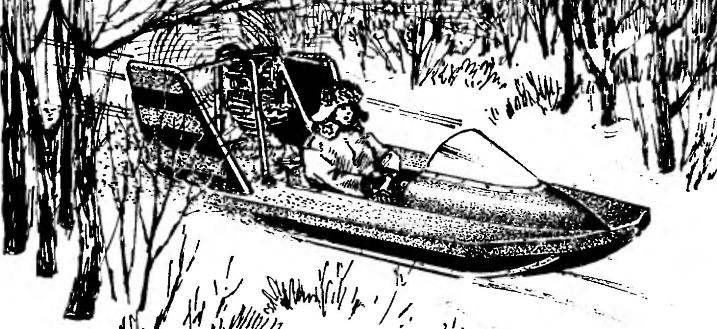
The engine of the snowmobile “Otter” — petrol, single cylinder, two-stroke power 18 HP And most importantly — homemade, made of components and parts various boat, motor and starter engines.
 
The CRANKCASE is cast from aluminum alloy AL2 setting the dimensions of the crankshaft from the starting engine PD-10M and has a similar “pleskachevskogo” Carter connector, tightened four bolts M8x1. 5 (in two planting holes are inserted steel control sleeve defining precision Assembly Carter) and two screws M6 (bottom).
 
Pollicina groove landing surfaces crankcase parts was carried out on a lathe with the use of simple tools.
 
 
Main technical characteristics of the snowmobile “Otter”:
 
Length, mm……………………………………….3110

Width, mm…………………………………… 1460

The height of the air screw, mm…… 1647

The diameter of the propeller, mm………. 1200

Full weight, kg……………………………… 180

Specific pressure on the snow, kg/cm2…..0,026

Maximum speed, km/h……………..70

Cruising speed, km/h………………..35

Engine power, HP……………………. 18

The stock fuel tank, l…………………………5

 
Short engine specifications snowmobiles
Powerplant snowmobile
Powerplant snowmobile “Otter”:
 
1 — the body of the snowmobile; 2 — fuel tank (plastic canister with a capacity of 5 l); 3 — air cleaner to carburetor; 4 — magneto M24; 5 — motor; 6 — rotor; 7 — cylinder; 8 — arc motor frame; 9 , the starter pulley

 
Motor frame
Motor frame:
 
1 —arc (pipe 22×2, 2); 2— cross member (tube 22×2); 3 — solitaire (steel, sheet s2, 4 pieces); 4 — yoke engine mounts (tube 22×2, 4 pieces); 5 — a clip of fastening of a strut of aerodynamic keel (pipe 16×2, L20, 2); 6—Circlip (wire d6); 7—starter pulley (D16T, d70); 8 — clip fastening to the body of the snowmobile (tube 22×2, 4 PCs.)

 
Node mounts the engine to the engine frame: 1 —burst of engine; 2 — rubber Bush; 3— a clip of fastening of the engine; 4-bolt М8х 1.5; 5 — cotter pin; 6 — washer; 7 — the engine cross member frame; 8 — solitaire
The node mounts the engine to the engine frame:
 
1 —tide of the crankcase; 2 — rubber Bush; 3— a clip of fastening of the engine; 4-bolt М8х 1.5; 5 — cotter pin; 6 — washer; 7 — the engine cross member frame; 8 — solitaire

 
Fixing unit motor frame to the body of the snowmobile: 1. the engine frame; 2 — rubber Bush; 3,7—bolts M8x1,5; 4 — bracket (steel, strip s3); 5 — stringer under engine frame (70x20); 6— 3x20 screws (2 PCs): 8 — 25x25x3 washer with welded nut M8x1,5; 9 — pin
 
The fixing unit of the engine frame to the body of the snowmobile:
 
1. a motor frame; 2 — rubber Bush; 3,7—bolts M8x1,5; 4 — bracket (steel, strip s3); 5 — stringer under engine frame (70×20); 6— 3×20 screws (2 PCs): 8 — 25x25x3 washer with welded nut M8x1,5; 9 — pin
 
The attachment point of the aerodynamic keel to the motor frame
The attachment point of the aerodynamic keel to the motor frame:
 
1 . a motor frame; 2— brace (pipe 14x 1); 3 — keel, 4 — clip on the arc motor frame; 5—finger d6; 6 — fork brace (steel, strip s3); 7 — weld-nut M6; 8 — M6 bolt; 9 — washer; 10 — rubber bushing; 11 — pin

 
System manual start engine
System manual start engine:
 
1 — flywheel; 2 — Circlip; 3 — starting pulley; 4, the starter cord
 
The attachment of the propeller

The fixing unit of the air vnta:
 
1 — engine flywheel (PD-10M); 2— screws M8 (6 PCs); 3 — locking (wire 01); 4 rotor; 5 bot M8x1. 5 (4 PCs); 6 — nut М14х1,5 with pin; 7 — flange (s5); 8 — hub

 
Hub of the propeller
The hub of the propeller:
 
1 — nut M8 (6 PCs): 2 — housing hub; 3 – bolt M 14×1,5

 
The mechanism of the throttle (
The mechanism of the throttle (“gas”) carburetor:
 
1 — handle course (with the button “stop” of the engine); 2,7— stops sheath “gas” (area 20x20x5); 3,8—conduit “gas”; 4—the grommet (rubber); 5 — lever “gas”; 6 — wire throttle

 
Engine dimensions
Engine dimensions
 
The layout of the engine parts in the crankcase
 
The layout of the engine parts in the crankcase
The layout of the engine parts in the crankcase:
 
1 — the rear part of the crankcase; 2 — stud M10x1,5 for cylinder mounting (4 PCs); 3 — rod of the piston (from the engine PD-10M): 4 — front sump; 5 — coupling the drive magneto (PCB); 6— segment dowel 5×9; 7 — clutch ignition timing; 8 — fastening screw M6 magneto (3). 9 — fastening screw M6 semi-clutch; 10,17 — cuff 1-30×52-1; 11,16 — bearings 2206; 12 — spacer washer (3 PCs.); 13 — a cranked shaft; 14 — gasket; 15 — the bearing 206

 
Device
The device of the button “stop” of the engine:
 
1 — pressure plate element (plastic); 2 — spring; 3 — body; 4 — contacts (copper); 5 — screw (3 PCs); 6 — handle (rubber); 7 — lever; 8 — cable; 9 — bushing-insulator
 
Layout engine
The layout of the engine (operating position of the engine on the engine frame cylinder down):
 
1 —flywheel (engine 11Д-10M); 2,3,4 — cylinder liner, cylinder and cylinder head (from a motorcycle “IZH-Planeta-3”); 5 — ignition plug; 6 — piston (engine PD-10M); 7— carb-TO-36И; 8 — inlet connector (“IZH-Planeta-3” or improvised): 9 — magneto M24; 10,12 — side of the crankcase; the crankshaft 11 (engine PD-10M)


The purge channels and all interior surfaces are carefully finished by hand.
 
The tightness of the crankcase seals and rubber reinforced cuffs.
The CRANKSHAFT, as already mentioned, from the “poscache”. To install the driver half of the coupling of the magneto front end modified: first, a little shortened; secondly, in his neck of the selected slot under the Woodruff key; third, drilled an axial hole with M6 thread for screw mounting of the coupling halves.
In the crankcase, the crankshaft rotates in three bearings: on the front shank it is wearing one bearing is a roller 2206, the rear two — roller 2206 and the ball 206. Channels the lubrication of all bearings is extended. In addition, the shanks wearing the three spacer washers 1 mm alsenoy: one in the front and two at the rear.
 
Crankcase
The crankcase:
 
1 — back (aluminum alloy AL2); 2 — stud M10x1,5 for cylinder mounting (4 PCs); 3 — front (aluminum alloy AL2); 4 — bolt M8x1. 5 (4 PCs); 5 — installation sleeve (steel, 2); screws and bolts, tightening of the case, detailing not shown; dimensions are given taking into account the thickness of the gasket between the parts of the crankcase

 
Revision of the crankshaft
 
The FLYWHEEL is also from the PD-10M. The perimeter of its rear end drilled six holes with thread M8x1. 5 screws for attaching the hub To the last four bolts M8x1. 5 docked propeller. Screw heads and nuts to hub bolts scontrini in a circle of steel wire.
 
CYLINDER with sleeve, from the engine of the motorcycle “IZH-Planeta-3”, dragged to the crankcase by four studs M10. In the right side of the cylinder (in the lid of the overflow channel) drilled three holes: two M5 screw for mounting diaf-Rahmanova pump and one for the fitting the rubber hose, which is a cavity passageway is connected to the fuel pump.
 
PISTON with rings and piston pin is also from the PD-10M. Only the piston skirt cut extra Windows with a size of 30×30 mm.
 
The drive COUPLING of the magneto turned on a lathe from the PCB. Has a groove under a leash coupler ignition timing and the key groove.
 
MAGNETO type M24 with clutch ignition timing is attached to a specially molded to flange the front of the crankcase with three screws M6. From magneto to the engine button “stop” stretches the cable with two wires.
 
The working direction of rotation of the crankshaft is specified by the type of magneto (left or right rotation). And again. If you change the geometry of the front flange of the crankcase, magneto is easy to install the alternator from the motorcycle “Voskhod”. In short, there are different configurations of the engine of the snowmobile.
 
The INLET fitting of the carb homemade, too, although it is possible the use of a modified pipe from a motorcycle “IZH-Planeta-3”. It is important only that the operating position of the engine cylinder down housing cover of the mixing chamber of the carburetor is not in contact with the magneto.
 
FUEL PUMP mechanical — from the boat motor Neptun; manual Tickler, embedded in the hose of tract “fuel tank — carburetor” from the boat “Surf”. Carb — TO-36И with a simple cleaner.
 
Such is the design of the snowmobile “Otter”, which I enjoyed for several years. Without any — even small — breakdowns.
V. PETROV, Krasnoyarsk Krai

Recommend to read

  • “CLAMP” THE BINDING“CLAMP” THE BINDING
    This files most often prescribed magazines sutured, piercing a few hole and tie them with lace. Offer a more simple method, take two identical slats on the size of the log the drilled...
  • DOORS FOR EVERY TASTEDOORS FOR EVERY TASTE
    The houses built on model design, mainly have a relatively comfortable layout. And yet it is impossible to consider the needs of each individual family, its growth and development. Have...