
 Commonwealth sports and equipment… When it comes to this topic, we are Olympic records with their fantastic results and sophisticated instruments, able to capture such results.
However, the automatic devices is not a privilege of big-time sports. An example of this can serve two exhibits in the section of “Young technicians” of the Central exhibition NTTM-74: backlit display-reflexometry and led spotlights for relay races. Both units are part of a complex intended for use in physical education classes. It was established at school No. 44 of the city of Gorky, under the leadership of physical education teacher M Sinitsyna.
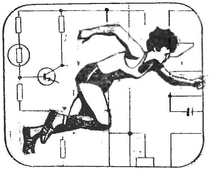
This is an unusual school gym, equipped with various instruments and devices (Fig. 1).
Training with the use of technology is not a novelty in pedagogy. And today, automation becomes an assistant and in the education of future athletes.
Devices gorkovchan simple, they can be made of the available materials. Such devices will be used at the departments of physical education universities, classes in technical and vocational schools, children’s sports schools.
THE SOONER THE BETTER!
The ability to respond to suddenly appearing signal or obstacle is one of the most important qualities of the person. “Perfect” reaction time help exercising, outdoor games, and training with the help of special devices — reflectometer.
Some of these devices is shown in figure 2. It is made in the form of an equilateral triangle with side size of 500 mm. On the front Panel — four hole-section, closed with a colored plexiglass or plastic wrap. In each section mounted in the lamp holder. Three sections, located at the base of a triangle, illuminate respectively the red, green or yellow. Fourth, the Central section has a white (“milky”) optical filter.
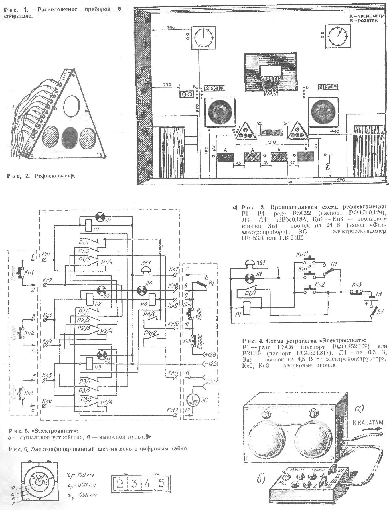
The class is divided into three groups and arranged at a distance of 4-5 m from reflexometry. One person from each group take the remote button. Teacher or judge on the panel sets with the toggle switch type of alarm: light or audible. As soon as he presses the “start” button flashes a white light or the bell rings, and runs electroeconomy. At this signal each of the three participants needs as quickly as possible press the button. The one who manages to do it first, at the same time turns on the lamp “own” the colors and stops the stopwatch. When this button is automatically disabled opponents. The reaction time captures the time.
The “Reset” button the device is reset, and there is a change of competing.
Scheme reflexometry presented in figure 3. The teacher clicks Кн4 “start”. Relay R1 cambiocorsa, including simultaneously your contacts R4/1 and R4/2 warning device and stopwatch, ES. The signal may be audible (bell Зв1) or light (light L4): it is selected by switching the toggle switch B1.
When you press the buttons KN1, Кн2 or Кн3 actuates the corresponding relays R1—R3 And any one of them while the other two de-energizes and stops the stopwatch ES. In the initial state of the scheme is provided by clicking Кн5 “Reset”.
Relays R1—R4 installed in the housing Board. Button Кн4, Кн5 and the switch B1 are mounted in a separate remote control of the teacher (judge). The buttons KN1—Кн3 remote. The remote and the remote button are connected with the device via a flexible insulated wire.
“ELECTROCOAT”
In the upper part of the gymnastic of rope under the leather or rubber ring mounted micro switch button with a pair of no contacts. Such rings and buttons can have more than one, at different levels. The wires connecting the microswitches with a signaling device woven into the rope.
The signal device consists of a light bulb, bell and switch “altitude”. Once a student reaches a given height, he grabs the rope in place of the microswitch and thereby includes signal lamp and bell.
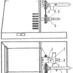
The signal received off of the wire, to trigger the electromagnetic relay R1, which, in turn, contacts R1/1 applies power to the lamp L1 and call 3in1 (Fig. 4). The serviceability of the signal devices check button Кн2 connected in parallel with the microswitches KN1. Click Кн3 “Reset” the scheme lead to its original state.
To power just device enough the two parallel-connected battery 3336L (KBS-L-0,5).
The signal lamp L1, the call Зв1, relays R1 and battery B1 is mounted in a separate housing (Fig. 5A). Button Кн2 “Test”, Кн3 “Reset” and the switch W1 “height” installed on the remote panel (Fig. 5B). In one case it is recommended to install two or three sets, the number of gymnastic ropes, available in the room. Signal lamps are painted in different colors. Housing side mounted jacks or terminals to connect wires from cables and remote control.
WHO IS THE MOST ACCURATE!
Throwing the ball into the goal to develop hand-eye, agility, strength. However, to the eye I guess the result is sometimes difficult: the ball bounces off the target instantly, keep track of them difficult. But the electrified target will mark all hits.
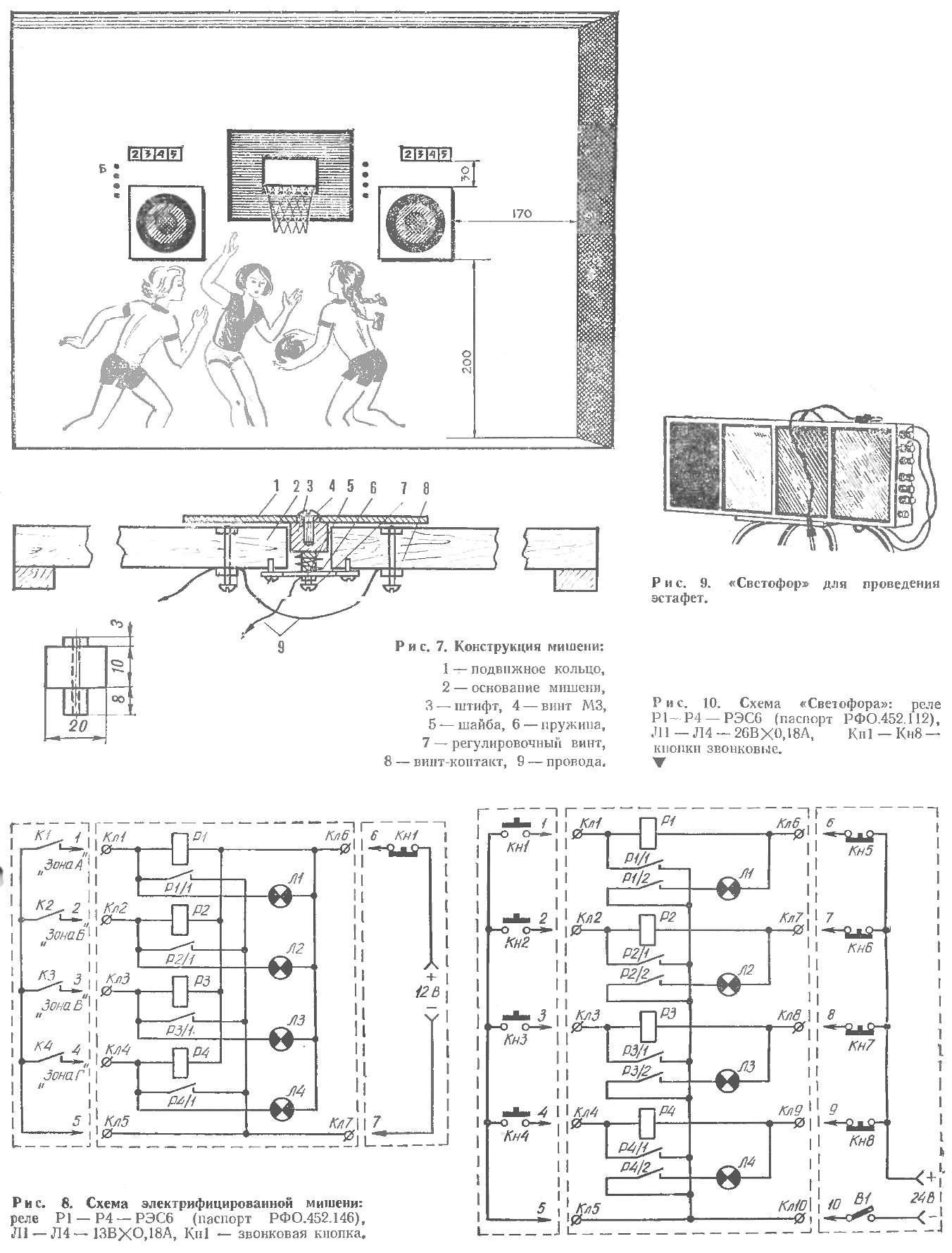
In the center of a square of size 1200X1200 mm (Fig. 6) there are three movable rings-zone painted in different colors: the inner (A), middle (B) and external (In). Area And painted in blue, area B in yellow, the area In red. The rest of the square shield (G) painted white. The width of each zone is 300 mm. Ring zone made of duralumin with a thickness of 2-3 mm, the target base — made of organic glass or plywood with a thickness of 12-15 mm.
Shield design target is shown in figure 7. The movable rings are attached to the iron or brass pins move freely in the holes of the base. The pins has a through hole with a thread M3 screws. With their help, the pins are attached to the ring area and washer that hold the pin. On the ledge of the pin fits over a spring, tending to push it out of the hole. The free play of the pin is regulated by the screw.
Zones A and B, respectively, are held by four pins, zone six and zone d is divided into four sectors each of which is secured by four pins. OTO need for more free pendants of zones and sectors on the basis of the target.
At the base of the shield at a distance of 1.5—2 mm from the surface of the moving zones and sectors set screws-contact: zones A and B — 4, iodine is area 6 and under every zone G but 3.
Contacts and screws connected the wires from the light Board. It is mounted in a separate housing divided by partitions into four compartments. They have a bulb flashing numerals 2, 3, 4 or 5. The top scoreboard is closed with a sheet of “milk” plexiglass. The schema of the target (Fig. 8) is mounted in one of the compartments scoreboard. Electromagnetic relays R1—R4 are connected with the contact 26″ and zones conditionally designated K1—K4. Parallel to the windings of the relay the lights L1 — L4 illuminated display.
When injected into one of the zones of the target closes the corresponding contact group K1—K4 and the result is displayed on the scoreboard.
Indications light displays off by clicking on a button KN1 Reset.
THE BATON HOLDS A “TRAFFIC LIGHT”
This device helps children develop dexterity and speed of movements. The appearance of “Traffic light” is presented in figure 9. Case rectangular 800Х230Х100 mm divided by partitions into four compartments, each of which has an illumination lamp. Top compartments closed with Plexiglas in different colors. For example, the first compartment is red, the second green, the third yellow, the fourth blue.
“Traffic light” mounted to the wall of the hall at a height of 2-2,5 m from the floor. Below, at a height of one meter from the floor and at the same distance from each other are four bell buttons.
The class is divided into four teams. Relay participants must take turns to overcome the distance and press the button with the number of your team, to enable the cell Traffic light.
Diagram of the device in figure 10. Relay coil R1—R4 is connected to the power supply via closing contact of the buttons KN1—Кн4 “start” and NC contacts of the buttons Кн5—Кн8 “Reset”. Operating, relays R1—R4 cambiocorsa and at the same time contacts R1/2 — R4/2 include corresponding lamp L1—L4 illuminated display. Lamp off by pressing the button Кн5—Кн8. Together with the switch B1 is mounted in a separate portable remote control, are a teacher or judge.
A MATTER OF SECONDS
Clocking time in the competition but the sprint running or skiing, using only the usual stopwatch, hard: often there are annoying lining, failures and errors in determining athletic performance. To help the sport and here comes the technique.
Automated start finish installation allows to record the time taken to run short and medium distances with an accuracy of 0.01 s simultaneously on two treadmills. The launch of the scheme (Fig. 11) is carried out from the starting pistol SP, which, together with the shot of their contacts includes electroeconomy ЭС1 and ЭС2. While runners complete the distance, relays P1, P2 blocked, and the clock continues to count down the time. When there is a failure of the finishing strips, the contacts K2 and KZ are opened, and the clock must be stopped, showing the time of passage of distance runners”.
The device is mounted in a metal or wooden case (Fig. 12). The front panel contains two lectromechanical stopwatch type P3-53Л or NV-53SHCH, signal lamps L1 and L2, terminals for connecting the starting gun and the finish line contacts, the power switch Q2. If there is no stopwatches PV-53Л or PV-53SHCH, you can use electroeconomy produced by the plant “Ofispring”. They can be found in any school physics laboratory.
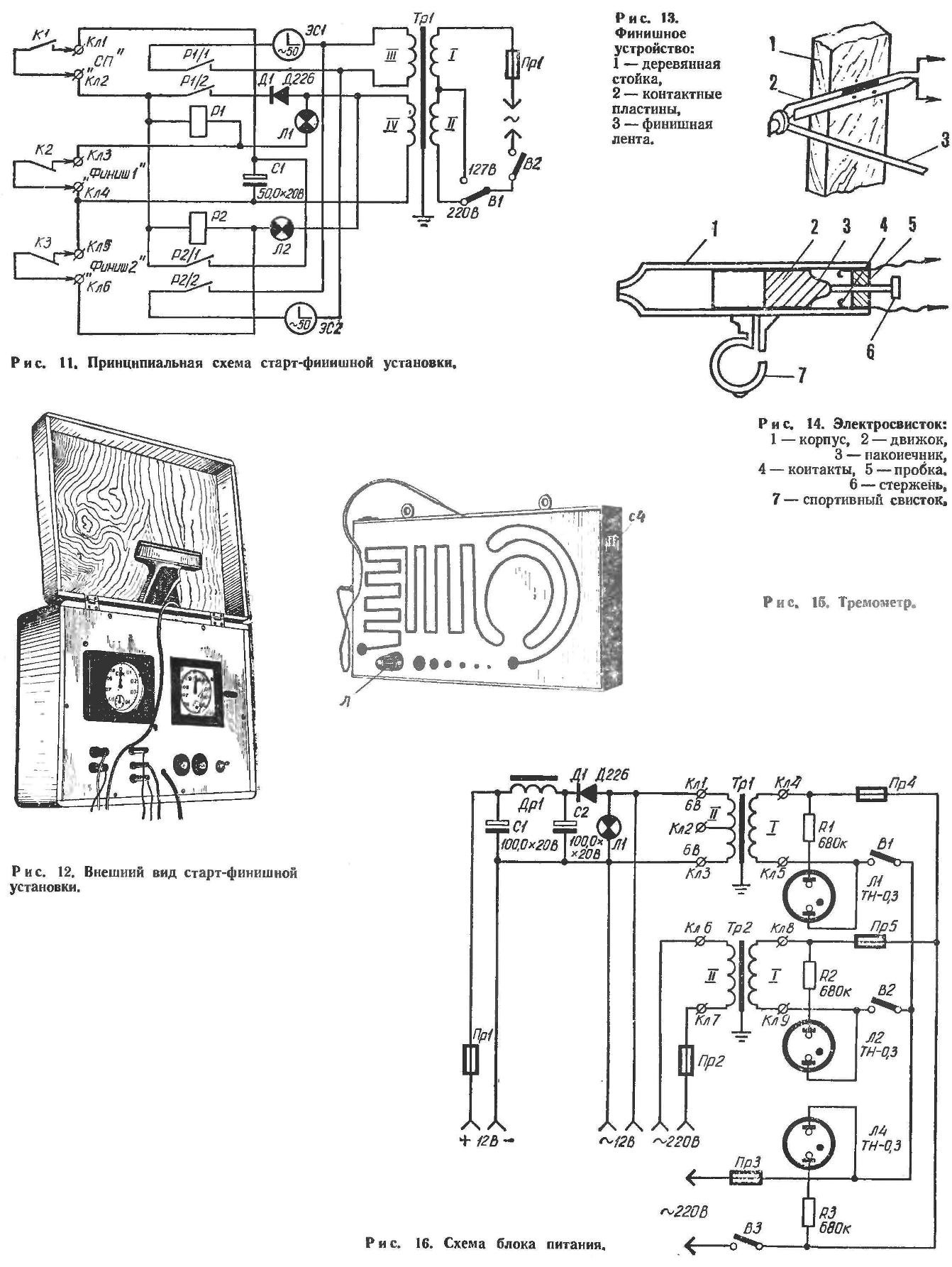
The finish of the contact device comprises two contact plates, mounted on wooden stand (Fig. 13). The Stoics are installed on the finish line, and between them stretched the finish tape. The ends of the tape are fixed on the contact plastics so that they were locked in a tight ribbon.
At the time of failure of the finish ribbon runner the contacts open.
Instead of starting gun can apply a firecracker with contacts or electroswitch.
Electroswitch (Fig. 14) is a wooden or plastic case, inside which there is the engine with metal tip. Inside the case the engine with the rim” moves, closes its tip contacts. Contacts fixed with the help of tubes through which pass: t-rod to return the engine to its original position. The bottom of the casing is a hole in which is inserted a sports whistle.
Now for the details of the scheme. P1 and P2 — compact electron and RIT relay РЭС6 (passport of the RFO.452.100), the filter capacitor C1 К56-3, signal lamps L1, L2 — 26Вх0,18A, TP1 — down transformer: core Ш20х30, winding I comprises 840 turns of wire PEL of 0.25, II — 620 turns of PEL of 0.3, III — 795 of turns of PEL 0,2, IV — 176 turns of PEL of 0.5.
IN THE EXCERPT — THE SUCCESS OF
To work precision movements, to make them more coordinated help of exercises using special devices — termometro. Such a device will serve a useful service in the school, and Mr. Ohm.
Trimmer shown in figure 15, has a notched cut-outs of three types, respectively is designed to generate horizontal, vertical, and rotational movements. The path length of all sections of movements 1 m.
Part of termometro is a metal probe Ø 1 mm with insulated handle connected to the device by flexible wires segment.
The subject, holding the probe in his outstretched pvкe should protest them along the slot without hitting its wing. In case of an error lamp flashes and strobes the counter.
For the training of tremor in statics are five round holes with a diameter of 20, 15, 10, 7.5, and 3 mm, located in the lower part of the device. The probe is alternately inserted into these holes, holding it at arm’s length for ten seconds.
Electrical diagram trimmer and relatively simple. A series circuit consisting of a recording device (a lamp L, CQ counter) and battery power, closes a pair of contacts “thermometrically tablet — probe”. Mid — four-digit electromagnetic counter (passport PC2.720.002). L — lamp, 6.3 V.
This device is assembled in a wooden or metal case size 500X300X100 mm. faceplate tablet with cutouts, made of sheet duralumin with a thickness of 1-2 mm.
To use termometro in physical education classes are advised to make their 3-4 sets. Devices hung on one wall of the gym at a distance of 1 m from each other, at the height of the shoulder of each student.
The power supply is shared for all devices (Fig. 16). It consists of a step-down (TP1) and the separation (2) transformers, myprimetime.
Both transformer is assembled on the U-shaped core. Primary (AC) and secondary windings wound on separate bobbins. Such transformers are widely used for demonstration experiments in physics lessons.
On the back wall of the unit casing is mounted the power connector through which power is supplied to the devices. The magnitude of the supply voltages indicated on the diagram.
Yu was VERHALE, candidate of biological Sciences
Recommend to read
 UK-4: MORE ABOUT THE NEW FEATURES
In last year's fourth issue of the journal, I read an article about Razakhatskaya V. the machine "Skillful hands". There is proposed a device for drilling. But it will have to cut off part...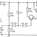 POWER SUPPLY WITH ACTIVE FILTERS
For portable electronic equipment need a small volume and weight of the power supply. To solve this problem relatively simply by replacing passive LC and active RC filters. The...
