 CHARGING AND RECOVERY DEVICE’S BATTERY. The battery in the car is one of the most important elements. Despite the constant efforts of manufacturers to improve the reliability and durability of the batteries after 3 — 4 years they still come into disrepair, aided by a constant undercharge when riding in urban environments the cost of the battery remains high, so to extend the term of its service makes sense at least once in the summer season to carry out remedial exercises.
There are devices that are able in some degree to return capacity to the battery by discharging the battery at the active load (resistor) during negative half cycle. The discharge currents depending on the battery status can be 200 — 500 mA. Such devices are simple enough to manufacture, but the quality of the restoration they provide.
In one of the magazines in 2005, was found an article by V. Konovalov and A. Urazgildeev “restore the battery”, which is the technique of bringing to a healthy state of the battery and the circuit device.
For readers I will quote the meaning of restore batteries with the polarity reversal method “To translate coarse sulfation in the amorphous lead, you need a power of 1500 watts, the temperature of the electrolyte should not exceed 42°C. Further heating leads to warping and circuit plates.
To reduce heating of the electrolyte, the pulse time must not exceed 3…5 MS (Fig.1). Between the time of charge and discharge remains a gap in 8…12 MS, sufficient for cooling of the electrolyte. In addition, the pulse energy is consumed almost without loss for heating the surface of the plates.
The need for the discharge current is related to the fact that after the cessation of the charging current to the ions not reaching the surface zaalpersoneel plates, the next positive half-cycle does not have “acceleration” due to the small distance to the plate. The negative half-cycle removes ions from the crystals of lead sulfate.
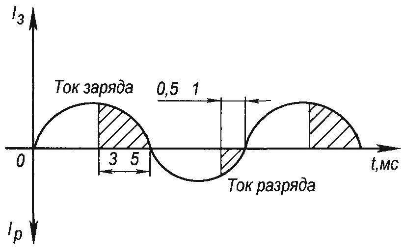
Fig. 1. A graph of the charge-discharge current
Reducing the surface area occupied by coarse grain lead sulfate, allows the charging-recovery-current to penetrate into deeper layers of the active mass on the surface of which has a working sulfation, easily recovering in the process of operation”.
Below is a modified I a simplified diagram of an apparatus for the recovery of batteries, which is easily manufactured and adjusted.
The device is intended for charging car batteries with capacity 75 ampere-hour. To restore a more powerful battery will require correspondingly more powerful transformer.
A block diagram of the charging and recovery of the device shown in figure 2, a circuit diagram is in figure 3.
As can be seen from figure 2, in the first half cycle charging current flows from the winding WII of the transformer through the diode VD1, thyristor VS1 on the positive terminal. Then with the negative pole of the battery closes to the second output winding of the transformer WII.
In the second (discharge) half-cycle the current flows from the winding WIll through the diode VD2, thyristor VS2 minus the battery and then its advantage is closed to the second output winding of the transformer WIll.
For proper operation of the device in the mode of charge—discharge windings being phased as shown in the diagrams (the beginning of the winding marked with a dot).
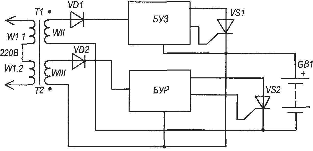
Fig. 2. The block diagram of the charging and recovery device (SOUND)
The units control the power thyristors in the modes of charge (BUZ) and discharge (BUR) are exactly the same. In contrast to the circuits of the control units in the mentioned article, the transistor analogs of discs work best when the thyristor is in parallel with him, which ensures its stable work on the formation of the control pulse. This ensures that the capacitor in each period is discharged.
Consider in more detail the work of one of the control units, for example, the charging (Fig.3). The analog of the dynistor, it only works in the positive half-cycle. With increasing current in the positive half cycle (Fig.1) increasing the voltage at the emitter of the transistor VT1, since the capacitor C1 is charged through the resistor R1. At the same time increasing the voltage on the base of the transistor coming from the divider R2, R5. There comes a point when the voltage at the emitter of the transistor VT1 reaches the level of 0.3 — 0.4 V more (relative to the minus bus) than at its base. The latter becomes a “minutee” emitter. This means that there is a condition in which the transistor opens. Its collector voltage becomes positive. Accordingly, the transistor VT2 opens. Resistor R4 is included in the emitter circuit of transistor VT2, a voltage is applied with positive polarity which is supplied to the control electrode of the thyristor VS1. The thyristor opens and the analog of the dynistor suspend its work. At this point, the capacitor is discharged not only through the resistors R1, but also through the emitter-collector junction of the transistor VT1.
Transistor VT2 plays a big role in creating the pulse. Voltage avalanche occurs not only at its emitter and at the collector. The base of transistor VT1 becomes more “minutee” emitter of this transistor. Happen sudden appearance of the voltage pulse with a steep front, which is very important for the operation of this circuit.
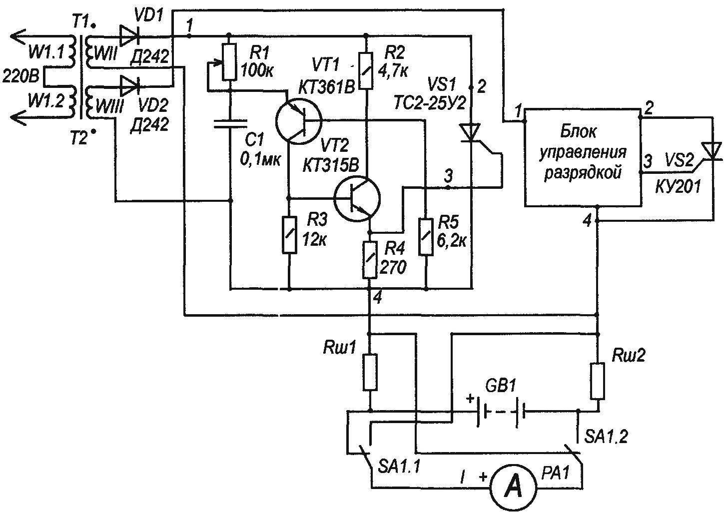
Fig. 3. Modified simplified circuit diagram of a SOUND
Depending on the duration of the charge of the capacitor C1 changes the time (moment) of the occurrence of the control pulse of the thyristor. What probably triggered the control unit from the beginning of the positive half-wave, the longer it will leak current through the open thyristor, the greater the charge current of the battery. Conversely, the later turns on the control unit in relation to the beginning of the positive half-cycle, the less time it will open the thyristor and, therefore, less charge current.
Thus, by changing the duration of charge of the capacitor C1 through the resistor R1, it is possible to change the charging (discharge) current of the battery.
This device used a transformer TS-180. Two secondary windings wound re-wire of PEV-2 2.2 mm (WII) and PEV-2 0,41 mm (WIll). They contain 65 turns, that gives idle 23 V. In principle, for the formation of the secondary voltage for the battery can be used a separate transformer. The most important thing when commissioning is properly “spaserovat”, — serviceable to both windings connected in series, and the output should be no voltage, i.e. both voltages included in antiphase.
The thyristor VS1 ME2-25У2 installed on theparameter area of 25 cm2.
According to the recommendations of the charging current is 3.75 A, and the discharge of 0.4 A. the charging Time and recovery process 3…5 hours.
The device uses a single ammeter, which via a switch SA1 is connected to control charge or discharge. Resistors shunts made of dual wire PEV-2 0,41 and 11 contain coils, the mandrel with the thickness of 6 mm.
When setting up instead of the battery more convenient to connect a light bulb at 12 V.
A. PARTIN, Ekaterinburg
Recommend to read
 NIGHT TRAP
Suspended in the area, it will distract on itself, annoying insects, and gardening can be destructive to pests. The secret simple trap, judge for yourself. In a flat... NO INJURIES
When sharpening saws with a file, if it is not docked, holding her hand runs the risk of injury from sharp teeth. To avoid this, make of a segment of hose to the loser at hand — work...
