The basis of the timing part — timer on the chip DD1 and DD2. When switching on the supply voltage DD1 chip set — via reset circuit RЗС1 — zero (the log. 0) and R6-trigger — through the chain R16С6 in the unit status (log. 1). Then the output 4 DD3.2 and input 2 DD3.1 will log.Oh, and the output 3 DD3.1, connected to the reset input I chip DD 2, — log.1. The counter-divider when this is cleared to zero count.
A master oscillator (on-chip DD1, resistors R4, R5, R11 and the capacitor C2) generates a pulse from 175 to 280 Hz. The frequency is changed by the variable resistor R11. The period of oscillation of the pulse generator at the middle position of the engine is around R11 4,58 msec. Resistor R4 limits the discharge current of the capacitor C2.
Through connections inside of the chip DD1 pulses of the main generator G is transmitted to divider ST. The period of generation is increased to 32 768 times, and the output signal S1 occurs with the oscillation period of 2.5 min. the Last applying to the input of C2 of the microcircuit DD1, divided by 60. Thus, the output M IC 001 produces pulses having a period of 2.5 hours
Output M IC DD1 first positive differential voltage appearing approximately 1.5 h, passes through a differentiating chain R13С4, resistor R17 and entering at input 1 of logic element DD3.1, this switches the RS-trigger. Output 3 DD3.1 voltage appears on the output 4 DD3.2 — voltage high level. Last through a resistor Я19 opens the transistors VTЗ and VТ4 current amplifier; relay K2 releases and contacts K2.1 connects the heating element RL to the power network.
The voltage taken from the output 4 DD3.2, is fed to the input 13 of the lock DD3.4, which, by acting on the enable input signal, the transistor VT1 closes, causing the thermostat is disconnected from the power supply.
At the same time the voltage of the low level supplied from the output 3 DD3.2 to the input I of chip DD2, enables the divider to 6. The pulse S1 is supplied to DD1 CP DD2 chip. Then at pin 5 of this IC is obtained a signal with a period of 15 min, which, entering at entrance 6 DD3.2, switch R6-trigger, and the output 4 DD3.2, a voltage is applied to the low level. Transistors VТ 1 and VT2 are closed, relay K2 releases the armature and contacts To 2.1 disables the heating element RL of the defroster from the mains.
The signal received at the input 13 DD3.4, is applied to the enable input. The lock opens and the thermostat is connected to the current amplifier. The dividers on the chip DD1 and DD2 are set to zero, and R6 is a trigger in a single state.
With the advent from the conclusion of 10 DD1 the next pulse, the positive difference which in the steady state is repeated every 2.5 h, the defroster will turn on for 15 minutes To power the device from AC voltage of 220 V has a built in adapter with a step-down transformer T1, a bridge rectifier VD3—VD6, 9-volt voltage stabilizer DА2 and capacitive filter C7—C9.
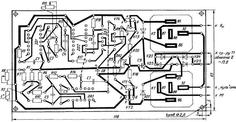
All components (except transformer T1, the thermistor R2 type MMT-1, and the variable resistors R8 and R11 type JS4-1) are mounted on the PCB size 118x65x1,5 mm of one-sided foil fiberglass. Fixed resistors type MLT-O. 125. As the capacitors C1—C7, it is recommended to use K73-9, and C8 and C9 electrolytic K50-16. Semiconductor diodes — silicon: КД102А (VD1, VD2) and КД106А (VD3-VD6).
Silicon transistors also. At the inputs — КТ315Г with the ability to replace КТ3102А (VT1 and VT3), in the output — КТ815А or КТ817А (VT2 and VT4) that are installed vertically, without the radiator. IC: DA1 — К554САЗ, DA2 – КР142ЕН8Г, DD1 – К176ИЕ12, DD2 — К561ИЕ8, DD3-К561ЛЕ5.
Electromagnetic relays automotive type 113.3747-10, powerful contacts which can withstand repeated inclusion of compressor motor M1 and the heating element DH of the defroster. Transformer T1 power 2-4 watts (used in many adapters of industrial manufacture).
Debugging mounted printed circuit Board is performed when disconnected from the refrigerator condition. Instead of the load (the motor M1 and resistor RL), use the usual table lamp.
Expansion of the device needs to be responsive to temperature changes in the range from minus 14 to plus 4°C. However, to deal with the cold when debugging electronics is difficult, so it is recommended to replace the stock R8 resistor 1.5 kOhm. Then adjust the thermostat, you can have more available for this range: plus 18-40°C. And to accelerate the adjustment work on the timing of the device is recommended to reduce the capacitance of the capacitor C2 is a hundred times, then the period of the pulse output from the M chip DD1 will be reduced to 90 C.
Checked and adjusted the device (after the restoration of the elements required by the scheme) to be mounted in the refrigerator.
G. SKOBELEV, Kurgan

 In refrigerators with mechanical regulator temperature measured on the evaporator. It happens that the evaporator becomes covered with frost, and the thermostat begins to operate with an error, making failures in work of all lagoapraia. To combat this unwanted phenomenon (including — with the advent of frost) refrigerator has to periodically disable. In some designs there is a semi-automatic defrost mode, which the system is embedded a heating element with the corresponding button.