 Kit electronic Christmas decorations from four independent devices developed and produced by the student of 9th class member directorship radio children’s Palace of creativity from the city of Saransk Alexei Pichushkin. On the urban exhibition of technical creativity in 2004 with these decorations won first place.
Switch garlands
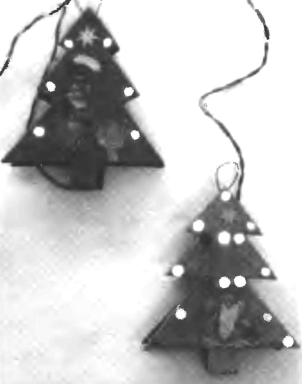
This device is a flat tree (from any rigid sheet material), decorated with four flashing led lights. Schematic diagram of the device presented in figure 1A.
In the scheme there are two generator of rectangular pulses. One is executed on the logic elements DD1.1 and DD1.2. From its output signal is supplied to the inverter DD1.3, forks: one part is supplied to the transistor VT2, and the other through the inverter DD1.4 — on the transistor VT1. Due to the fact that the signals are out of phase, the transistors are opened alternately, and also alternately switches the lights HL1, HL5, HL9 and HL2, HL6, HL10, included in the collector circuit of transistors.
The generators with their inverters are made on the elements of DD2.1 — DD2.4, works the same as the first, but with greater frequency. He alternately switches the transistors VT3 and VT4, which respectively include garlands of LEDs HL3, HL7, HL11, and HL4, HL8, HL12. Resistors R3, R4, R5, R6 limit load current to the logic elements DD1.3, D1.4, DD2.3, DD2.4. The Zener diode VD1 and resistor R9 form a voltage regulator power supply circuits.
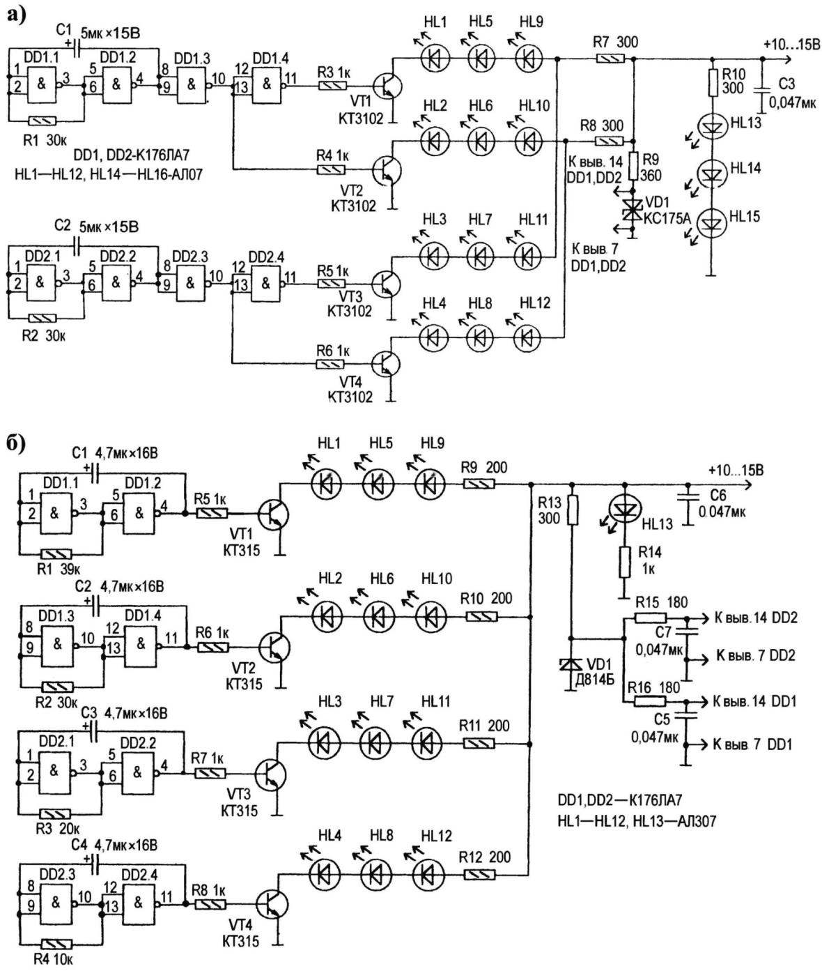
Fig. 1. An electrical circuit switches lights:
— controlled by the two generators; — control from the four generators
A second device similar to the first: also a tree with four led lights. A schematic diagram is shown in Fig. 1B. But, unlike the first, the lights are controlled by four separate generators operating at different frequencies. The first of them assembled on the logic elements DD1.1, DD1.2; the second on DD1.3, DD4; third in DD2.1, DD2.2 and fourth in DD2.3, DD2.4. Generators controlled by transistor keys VT1 — VT4, which include the corresponding led lights. Resistors R9 — R12 limit the current through the LEDs. Resistor R13 and Zener diode VD1 constitute a voltage regulator power supply circuits DD1 and DD2. Chain R15 — R16 and C7 — C5 — decoupling, They reduce the impact of generators on one another through food chains.
Musical garlands
The following device (Fig.2) is this kind of music. In this music the signal from the chip DD1 controls four groups of strands of five LEDs each. DD1 chip along with the function of a music synthesizer is the reference generator, the signal CC which is pin 1 DD1 through the amplifier transistor VT2 is supplied to the count input of the binary counter DD2 (pin 10). Every 128-th pulse output 13 of the counter DD2 is CN input (pin 14) of a decimal counter DD3. The signals from the outputs of the counter DDЗ open the corresponding transistor switches that include led lights.
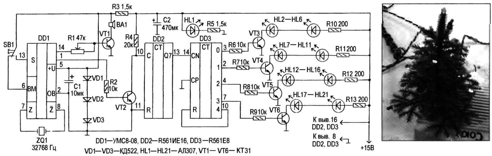
Fig. 2. Circuit diagram of musical garlands
The switching frequency of the lights is determined by the rhythm of the melody — and the result is a beautiful light pattern.
Indicator of the New year
This indicator (Fig.H) bit-for-bit provides an automatic ignition and extinguishing of the numbers of the coming New year on the scoreboard.
On the logic elements DD1.1 and DD1.2 made master generator of rectangular pulses, frequency of which depends on the resistance of the resistor R1 and the capacitance of the capacitor C1. The signal from the oscillator through the inverter on the logic elements DD1.3 and DD1.4 is fed to the input (pin 14) of the DD2 counter operating in the mode of the decoder. The outputs of the counter connected to the S – and R-inputs of triggers of a chip of DD3, and their outputs of flip-flops connected to the emitter repeaters on the transistors VT1 — VT4, which is loaded on the anodes homemade LEDs HL1 — HL4.
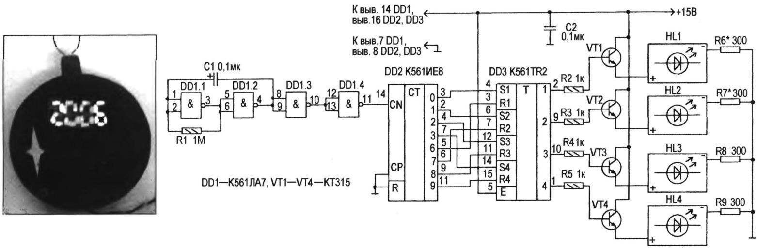
Fig. 3. Schematic and photo of digital display
The device operates as follows. A pulse frequency of 1 …1.5 Hz oscillator arrive on the DD2 counter, where the outputs of the 0 — 9 sequence, the high logic levels at the outputs 0, 1, 2, 3 are alternately transferred, in turn, RS-triggers chip DDЗ also in a state of high logic level on pins 2, 9, 10, 1. These signals allow the emitter followers in the transistors VT1 — VT4. This will cause successive ignition of the numbers on the indicators starting from the highest level. The next two pulses from the oscillator do not affect the condition indicators. The following four pulse generator will result in high levels at the outputs 6,7,8,9 counter that will translate RS-triggers in the zero state, causing the alternate locking of the transistors VT1 — VT4 and clearing indicators. The process is repeated.
Each digital indicator made of seven LEDs АЛ307. Emitting part of the LEDs moulded in the form of rectangles with dimensions 4×2 mm. Are the LEDs in the manner usual for seven-segment indicators. The findings of the LEDs are connected in such a way as to fire the desired figure. To ensure the same section of LEDs magnitude of the resistances of resistors R10 — R13 are selected depending on the number of connected LEDs in the relevant indicators.
Literature
I. F. Patchin. For the Christmas tree. The magazine “Radio”, № 11, 2002
J. ROGOZHIN
Recommend to read
 TWO-WHEELED TOW TRUCK
Motorists know that cars happen such failure when towing on a rope may not (when there is a fault in the steering control, brake system) or impossible (with some damage to the...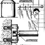 HOLD COVER
I want to suggest a simple method of fixing the bathroom rod for plastic curtain. After the repair you have lids from plastic jars, for example, from the Bustilat. They are easy to...
