
 For more than ten years, using a homemade device proved during welding, cutting metal sheets with thickness from 0.6 to 12 mm, the power at the time of starting the engine of a motor vehicle starter, charging alkaline and acid batteries, starting and subsequent operation of the DC motor power up to 1.5 kW. Moreover, I represent the universal — it is also an excellent source of safe voltage for electrical equipment, cellar, basement, workshop…
The homemade power transformer Cu—single rod (the cross section of the magnetic core of electrical steel 60×80 mm) with primary winding I, which has 230 turns of copper wire of diameter 2 mm, two secondary (II-1 and II-2 at 32 turns, the wire cross section in each — 32 mm2). This 25-kg-size (mm 280x240x120) electrical apparatus and winding III with 50 turns of wire with a cross section of 40 mm2.
Another massive and bulky IED — inductor Lc is also wound on the core type (section 40×30 mm — half-set of magnetic Vehicle), but with “air” gap, formed by 4-mm glass fibre laminate strip. It’s just two 60-turn windings of copper insulated wire diameter 6— 8 mm, connected in series.
A little away from the inductor Lc is the capacitor filter the type of CBGI total capacity of 2000 microfarads with an operating voltage of 80 V.
Under a Cu and Lc — rectifier unit, which includes two powerful electric valves D200 (VD1с— VD2c) and “locomotive” thyristor T160 (VS1с— VS2с) managed by the special unit on the chip with five transistors. Of course, all the applied power semiconductor devices on aluminum radiators.
Because during work (especially for welding and cutting of metals) higher heat, so far the unit comes with electric fan forced cooling (the motor M1 with the impeller on the shaft). It is located in the vicinity of the power transformer, so that more of the radiant surface came under air pressure.
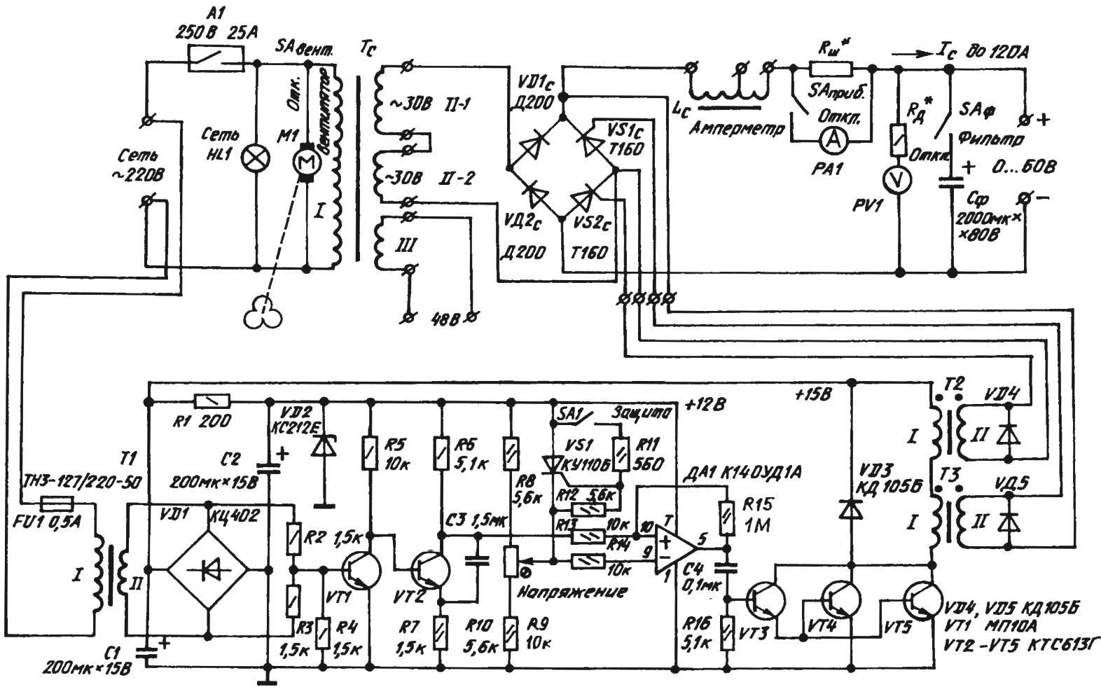
Fig. 1. Circuit diagram homemade welding-charger-starting devices
50-60 mm from the Vehicle is attached to the inductor LC, so that the Central part of the winding coincides with the Central axial line of the blower fan (for better airflow). Well, the rest forced air flow cooling is distributed between the power semiconductor devices and other elements and components of the device. The control unit thyristor. Mounted on a separate Board, it is located above the inductor windings perpendicular to it (Fig. 2).
The control unit thyristor is nothing like the phase switching regulator operation the diode-thyristor bridge rated for currents up to 500 A. Assembled from common electronic components and model components of industrial production, it provides high quality adjustment and the ability to secure fractionation in automatic mode.
There is also electronic protection of the Converter from abnormal events triggered by momentarily blocking the output pulses. This is an electronic device for the thyristor VS1 in the circuit of the control electrode which the sensors of the emergency state (for example, reed switches electric current limiters, contacts, mercury thermometers and similar compact devices) connected in parallel and operating on a short circuit PROTECTION (Fig. 1 shows only one pair of such contacts — SA1).
With the closure of any of the sensors of the emergency state is unlocked thyristor VS1, which subsequently and remains open. This means that the inverting input of the operational amplifier circuits DA1 receives the potential of exceeding all possible values of the sawtooth voltage at its non-inverting input. As a result, the output of “operatsionniy” is set to zero, the transistors VT3 — VT5 remain closed and the output pulses to the thyristors are not available.
Return the unit to its original state by briefly disconnecting the supply voltage of the unit.
Now some advice on the possible replacement of the electronic components. The role of transistors VT1 and VT2 are quite acceptable in more modern and widespread KT315 and КТ312; instead of three terminal transistors (VT3 and running parallel to the VT4 — VT5) only two semiconductor KT829.
As КД105Б (VD3 — VD5) it show any silicon diodes reverse voltage of not less than 100 V and a pulsed direct current of at least 3 A. Well, the rectifier bridge VD1 (Assembly КЦ402) can be replaced by any analogue from КЦ402 — KTS405.
“Silovik” T1 it is desirable to take ready— type TCEs or TCEs 70Л2-110L. Similarly, should proceed with the selection of pulse transformers T2 and TK. Of course, preference — industrial MIT-2B. However, if necessary, be satisfied, and the homemade “emulsijami” wound on any standard ferrite rings with a diameter of 20-50 mm. it is only Necessary to the primary winding of each transformer contained 50 turns of wire sew-0,2. Accordingly, in the secondary should be 150 turns of PEV-0,2. The beginning of each winding, it is recommended to allocate (for example, a color tag), not to make a mistake when soldering in accordance with the schematic electrical diagram of where the marks are conventionally indicated by dots.
The duration of the control pulses supplied to the thyristors equal to 100-200 µs.
In the author’s performance welding-charging-starting device is mounted inside a metal frame sizes 500x310x300 mm, made of steel area of 15×15 mm. In this design, almost one after another are: electric fan forced air cooling, power transformer, choke, rectifier unit, and the top (as already mentioned), the control unit thyristors.
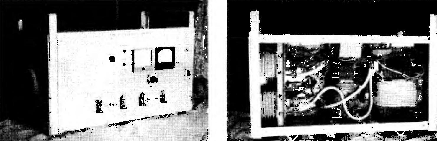
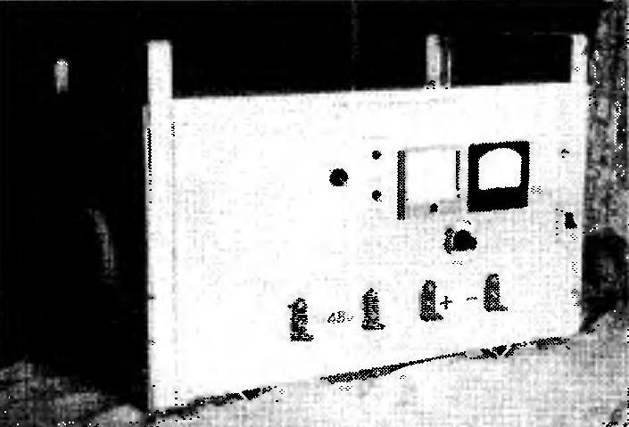
Fig. 2. Ready device (left) and its layout when it is removed the rear (right)
On the front panel installed: the mains voltage with automatic protection, signal light NETWORK, a DC voltmeter 30, measuring the gauge DC 50A toggle switch with AMMETER-OKL, a potentiometer VOLTAGE control unit thyristors, switches the FAN and FILTER off. Below, arranged in a single row terminals “+” and “-” to connect both to a car battery for its charging, and the starter for starting the engine of a motor vehicle when your battery is low, and in the mode WELDING for connection of a welding cable with electrode holder and “land wires” when welding and cutting metal, terminals ~ 48 V. Well under the top cover of the device mounted contact block with reversible copper bars for additional switching in a mode of WELDING and the CHARGER.
From my own experience, I recommend when you wire the device to achieve a particularly strong contact in all electrical circuits in accordance with circuit diagram. Power cables we strongly recommend to supply with bits of brass tubing, flattened and soldered terminal portion of each terminal, and then drill the hole with a diameter of 6.5 mm for fixing bolts. Moreover, all bolted joints to be fitted with washers for better retraction and obtaining a tight contact. This is especially true for the electrical connections of the power transformer, choke and rectifier unit.
As for the order of work on the welding-charging-starting device, there is, as they say, no problem.
In particular, when performing welding operations (WELDING) you want to insert a plug of a network cord in the socket (tracing to the phase wire went to the circuit breaker—for fast and precise actuation of electrical protection if the overload and short circuit). The inclusion of machine A1 should illuminate an indicator light NETWORK. You then need to connect the “land cable” (stretching from parts prepared for welding) to the ” – ” terminal, and the welding cable (coming from the electrode holder) to terminal “+”.
Turning on the blower fan air cooling device, disconnect the ammeter, which, otherwise, may fail. Remains inserted in the holder, the electrode, to select a potentiometer VOLTAGE adjustment valve bridge for the required current and begin welding.
Mode the CHARGER algorithm is somewhat different. Here already it is necessary to connect terminals “+” and “-” the appropriate conclusions from the battery, and a potentiometer VOLTAGE adjust “trolleybus” thyristors in the rectifier results required charging current.
STARTUP mode differs from a CHARGER in that in the terminal of the battery is fed a higher current up to 50A for a few seconds while turn on the car starter.
Main features
Voltage of the primary outlet, ………….220
Adjustable welding current, And……………….0-120
Adjustable charging current, And…………………..0-75
Adjustable output voltage, ……..0-70
Maximum power, kW………………………….3
Overall dimensions, mm………………..590x310x300
Weight, kg……………………………………………………….40
A. SHIKHANSKOGO, Volsk
Recommend to read
 ETERNAL LOOP
Metal soda cans and many canned goods now opened thanks to the special loop-shaped handle on the lid. And if the capacity is usually just thrown away, then the loop is easy to find... “NEW WAVE” IN THE OCEAN
A significant number of cruisers left in the Navy of the United States after the Second world war, some of which underwent major upgrades with the installation of a missile, not an...
