

 Busy with household chores or interesting conversation, we forget, for example, on a boiling kettle. Time to remind him maybe a simple buzzer. However, the oscillators sound frequency (e.g. multivibrators) based on transistor logic or integrated circuits do not always meet their creators. The simplest devices give a smooth tone, barely visible against the background of everyday noise, and sudden and loud “beep-beep” of a more complex designs can scare.
Another thing, if the signal is melodic, as, for example, musical greeting cards, which now receive widespread. They contain a chip DD1 synth melodies, a miniature power source, and ultra-slim piezoelectric alarm. Musical surprise comes to life when the card is revealed and the closed contacts of the power switch.
To accommodate such a detector to its melodic sound and timely remind the forgetful about the appearance of this or that situation, under any force. Enough to block the driven slider switch SB1, adding external parallel to the sensor detecting the status of household object, taken under electronic control circuit of power supply circuit postcard music device. The latter is easily separated from the paper, notched adhesive ribbons on the doors cards.
To switch SA1 in the state of the normally open contacts and associate them with the external sensor, proceed as follows. In place of the regular rolling of the tongue, drove the switch, place under the spring contact strip of electrically insulating material, each plane of which has its conductive layer for soldering the conductors going to the external sensor.
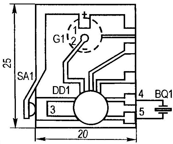
Fig. 1. The electronic “stuffing” of a modern musical greeting card
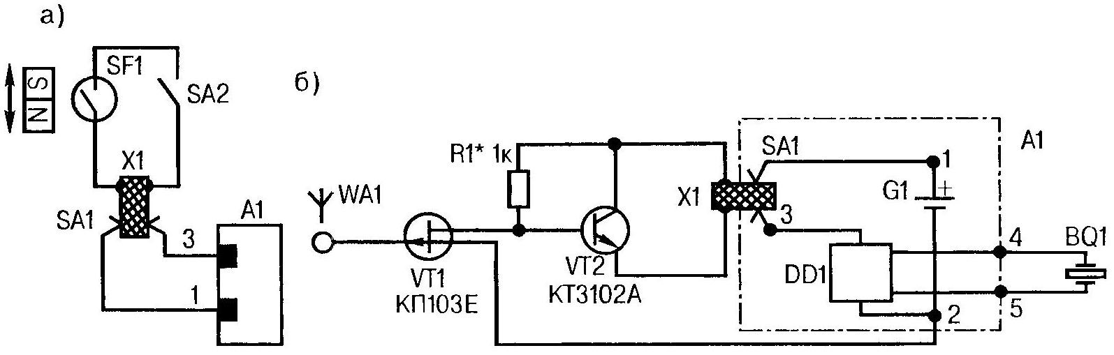
Fig. 2. Scheme for making musical alarm with a contact sensor (a) and the field-effect transistor (b) at the entrance
This insert can be cut from, say, bilateral foil, plastic or manufactured from cardboard with the subsequent bonding of the top and bottom of tinned copper (brass) strips. Recommended sizes — 13x6x1,5 mm. For the convenience of the layout of the household appliance music device and cut together with the adjacent portion of the card.
Now let’s look at some examples of practical use the musical alarm.
Many homes have an electric kettle “Tefal” or similar water heater with built-in automatic, which de-energizes the unit, as soon as the water comes to a boil. But accompanying the off click is so weak that no one hears.
Not to miss the moment of readiness of boiling water, can Supplement electric musical alarm fairly simple (Fig. 2A). The position A1 refers to the postcard music device overall, findings 1 and 3 which match those of the electrical contacts in the construction shown in figure 1. Between these contacts insert X1, conductive plates which are connected with the conclusions of the reed switch SF1, working for a short when approaching a permanent magnet.
The reed switch can take the most common (КЭМ1). Magnet — otdatsya security alarm system SMK or other common analogue. It should be mounted on the lever for the kettle, and the reed switch is just above the plastic strip between the side ends of the handle.
On the same lane, it is recommended to establish a fee, and the alarm of the alarm device, and microtubles SA2, the purpose of which is to turn off the alarm when the water in the kettle already boiled. SA2 turns on while you press on the button of the kettle.
Changing the reed switch modification with normally closed contacts, music device can be adapted, for example, for signaling loosely covered with the fridge. Work is minimal. Just need to fix a permanent magnet on the upper end of the door and the reed switch and music alarm on the refrigerator case. It is noteworthy that in this solution there is no need to switch SA2, because most of the time the door is closed, the reed switch contacts are open, the alarm device is silent, and electricity from a tiny battery cell is not consumed.
To modificirovat can happen and a pot of soup. However, it will have to change the type of sensor. Will tell him the idea, giving those interested by the design design.
Even schoolchildren know that water normally boils at 100 °C. Naturally, heating the same and the sides of the pan, where the water is. Diligent high school students a familiar and so-called alloy rose, consisting (by weight) 25% lead, 25% tin, 50% bismuth, and melting at a temperature close to 95 °C. So why not use this alloy in the sensor to the pot of soup boiling on a gas stove? Alloy rose, turning from solid to liquid, able to close a pair of fixed contacts in circuit music slot. When sound alert is heard, the fuse housing of the sensor can be separated from the wall of the dish and flip so that the melt was returned to its original position and re-hardened.
It is possible that a fan of tinkering will be more available wood alloy having a melting point of 75 °C. This material can also be used to fuse the sensor. But the correct operation is easily achieved by placing between the sensor and the heated to 100 °C pots of soup plate with good thermal resistance.
Using musical postcards, it is possible to build a signalling device (Fig. 2B), responsive to a relatively strong electric field. The invaluable help he will have, where you are dealing with home appliances powered by electricity 220 V. In particular, will allow to test whether the hull and fittings of the appliance under a dangerous voltage, that may be the result of aging or mechanical damage to insulation. Good field probing and identifying the loaded force chains among the many minor.
Music block A1 is enabled by using the sensor field VT1 transistor, which drives a bipolar semiconductor triode VT2 used in the circuit as the emitter follower. The latter is connected to the power circuit of the sound device pin insert X1.
While isolated antenna WA1 pin is not entered in the electric field, the transistor VT1 is opened Between the drain and source is small — of the order of 300 Ohms is resistance, which “grounds” the base of VT2 to a common wire (minus the source of G1) by holding “bipolaronic” in a locked condition. In the presence of an electric field transition resistance drain — source at VT1 increases to several kω or more. Semiconductor triode VT2 receives through the resistor R1 gate trigger offset and includes a signalling device, flowing current of the power supply, is approximately equal to 2 mA
Note that with some types of transistors are КП103 a device and a responding vigorously to touch WА1 hand. Such a characteristic allows it to be used as a sensitive sensor with a musical alarm, Respectively, and expanding the scope until the original sound alerts about the arrival of guests or call on the phone.
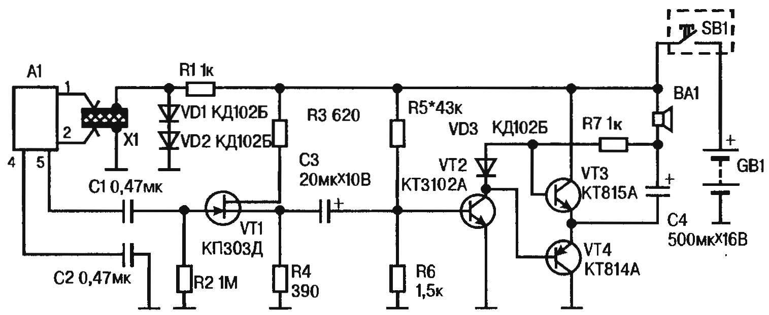
Fig. 3. Circuit diagram the musical elektrosvarka using the “postcard” generator ringtones
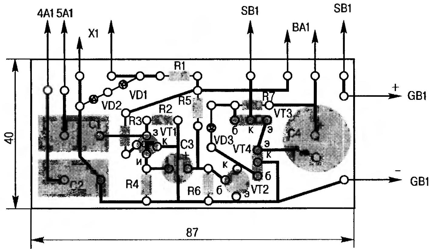
Fig. 4. A printed circuit Board, a homemade transistor amp with push-pull output, loaded on the speaker
The above was considered sound devices, where the electronic components from musical postcards played an independent role. However, very attractive the use of such a generator of original tunes as part of a modern electronic ringer, the sound power which is sufficient to cover the other strong sound sources. In this case, our jukebox needs to be supplemented by a booster, e.g. a transistor, push pull output stage (Fig. 3).
Since the release of music block A1, developing the “sound” voltage of about 1.2 V, is designed for very high impedance piezo, to the extent appropriate input impedance must have an amplifier. So, can not do without the matching cascade. In this case, we propose to execute it in the field-effect transistor VT1. With its low impedance source to the load R4 signal is removed, managing panoinverse cascade bipolar transistor VT2. That, in turn, the “rocking” push-pull transformerless amplifier, collected on transistors VT3, VT4 with different types of conductivity (n-p-n and p-n-p).
While the audio signal no voltage at the emitter VT3 and VT4, and the “minus” lead of the capacitor C4 should be equal to half the source voltage of the GB1. The desired mode is achieved by the selection of resistor R5 that sets the base of the transistor VT2, the bias is that on the shoulders of the divider formed by the resistor R7 and the n-p transition VT2, get about equal stress.
Due to the voltage drop across the diode VD3 VT3 VT4 base and have a small opening displacement. It provides economical quiescent current (2-4 mA in the collector circuits).
The arrival on base of VT2 positive half-wave of the audio signal a little more slightly open the transistor, causing a slight increase in collector current and the voltage drop across R7 while reducing the collector voltage. The corresponding negative shift of the receive voltage at the bases of VT3 and VT4.
The transistors of the output stage will react to this very peculiar: VT3 stronger lock, a VT4 are opened further, causing the voltage at the coupled emitters and the “minus” C4 will tend to the zero level to the common wire. As a result, through the sound coil dynamics BA1 current to flow from the source of GB1, which will swing the diffuser in one direction.
However, the state of transistors VT3 and VT4 with the arrival of the negative half-cycle of signal change. The voltage at the negative output C4 will tend to the level of the voltage source, through the head of BA1 current to flow in the opposite direction, moving the diffuser in the opposite (relative to the previously discussed case) side.
Of course, the above — only a simplified picture. But she allows to understand that the work is “rocking” the output push-pull cascade is inherently resembles a concerted movement of teammates, wielding a two — handed saw- a mechanical analogue of a single (VT3 and VT4) load. Becomes clear the process of strengthening as electric oscillations of the type “simple sine wave”, and a complex music signal, causing the speaker to output the melody, strength and power significantly exceeding the original coming from the beeper.
Since the inclusion of our musical call occurs when the closure door SB1 circuit common power supply GB1-type 9-volt “Crown”, to the extent and for the “postcard” music block A1, it is advisable to get it from the same battery, and not from the former miniature galvanic cell. For this wiring diagram provides for the use of a resistor-diode voltage divider R1VD1VD2.
The power supply circuit of music box A1 is joined with a call to the standard slip rings 1 and 2 by inserting X1 equal to the height of the replaceable galvanic element.
If you intend to make a music call with adjustable volume, then the concept of the device should be replaced by a resistor R4 and a constant resistance variable with the same value (type SP-0.4 or close to it). The remaining (unchanged) better suited widespread MLT-0,25. The capacitors C1 and C2 is not less than the available K73-P3, K73-9. Dynamic head can be of any type if only it had a capacity of 0.5—2 watts resistance voice coil DC current of about 8 Ohms. Power supply — “Crone”, 9 volt battery or two connected in series galvanic battery 3LR12.
The main part of a circuit diagram of musical bell is mounted on the circuit Board pseudospectral size 87x40x1,5 mm of one-sided foil plastic. The case for the assembled device can serve as a plastic box type soap dish of a suitable size.
P. YURYEV
Recommend to read
 CATAMARAN “FRISKY”
From the time of this writing I have built five catamarans of various designs. In designing, building and testing these boats took an active part my friend Anatoly Pavlovich Ignatchenko.... ELECTRONIC TRANSFORMER
A power transformer is to convert alternating current of one voltage to alternating current of another voltage at a constant frequency. The device in the normal "classic" transformer all...
