SOURCE THREE “STREAM”

SOURCE THREE For connecting various electronic and household devices designed for a constant voltage of 9, 12 or 15 V, requires adapter (the adapter from the network 220V). Usually every device it sells.
Meanwhile, there are many devices without adapters, but in some time the latter may be useful, for example, to power portable electric drill (screwdriver), which has lost energy output of the battery, or receiver, whose “exhausted”, or other similar event.
It must be sufficiently powerful and reliable power source, with automatic protection of output (triggered by a short circuit in the load) with the universality (outstanding various constant voltage) for use in the home.

The choice among the many published in the literature of the circuits of power supplies (adapters) allows to solve this problem, that is, on any “taste and color”. In my view, many of the published schemes is complicated, though, and provide, as a rule, any one of the above voltage.

Meanwhile, users often need a universal power supply, issuing two (and preferably three) different value of current. Besides radio Amateurs, especially those with little experience in electrical engineering, a more simple version of such a device with a minimum of parts.

Electrical schematic a powerful, stabilized

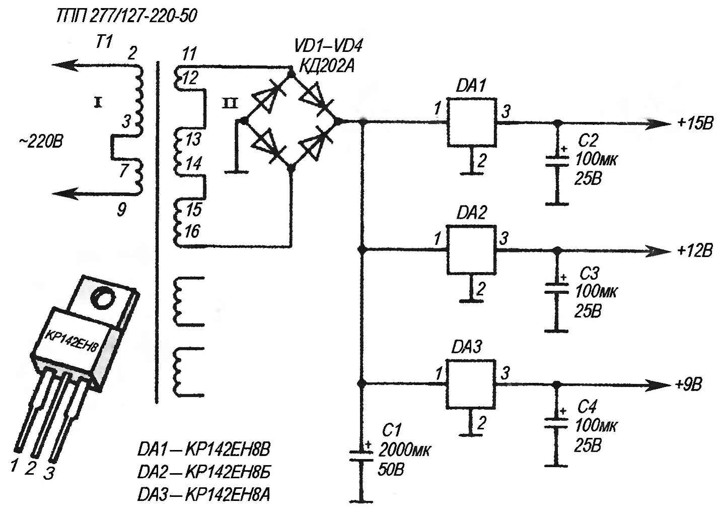
Electrical schematic a powerful, stabilized “trehoktavnogo” (outstanding voltage 9,12, and 15 V) power source.


Such a scheme displays a standard inclusion of integral stabilizers from КР142ЕН8 presented in the figure.

Manufacturer’s recommended input voltage range for microcircuits КР142ЕН8А—КР142ЕН8В is in the range from 14.5 to 18 V At the output of stabilized voltage, respectively, of 9 V, 14 V, 15 V, and 36 V. the Current output of one integral stabilizer with output voltage of 12 V in practice does not exceed 0.9 A.

An additional increase of the output current

Parallel connection of the stabilizers КР142ЕН8 that maximize the current in the load is a multiple of the number of stabilizers. If there is a need to increase the capacity of the power source, it is sufficient to connect in parallel (similar scheme) some more chips КР142ЕН8 in accordance with the required useful output current.

During the design the author chose the stabilizers КР142ЕН8Б (КРЕН8Б) because of their low cost and prevalence. They can virtually no negative effects to replace КР142ЕН18А — КР142ЕН18Б (which provides the ability to adjust the output voltage up to 26.5 V with the input 5 — 30V). In the last case the maximum net power output can be further enhanced, because the maximum output current is the integral stabilizer КР142ЕН18Б reaches 1.5 a at A voltage of 12 V.

Due to the presence of internal protection from short circuits in the integrated stabilizers КР142ЕН8 there is no need to install additional fuses in the device. Practice proved that if the consumption current in the load increases and reaches values of 5.5 and more, it will automatically reduce the voltage to 2…3, that will be safe for the device “load” the power source. The automatic decrease of the current in the load (below the threshold of triggering of automatic protection) output voltage stabilisers DА1 — DAZ is restored to the nominal during 10 MS… 12. In rare instances, protection will need to disable and re-enable the power source.

To check the maximum possible power of the stabilizer and its behavior with increasing-decreasing power load. To do this, before switching (high load), it is necessary at the output of the power supply as the load (active equivalent) to connect powerful wirewound resistor with a power dissipation -25 5 watts and a resistance of 9 to 15 ohms. As such an equivalent it is convenient to use a variable wirewound resistor SP5-30-1-25V which allows you to smoothly (linearly) to adjust the resistance from 0 to 18 Ohms, creating different equivalent loads.

Chip stabilizers are mounted on a common heatsink with cooling area 140 — 200 cm2. When working with a powerful load for a long time heats the radiator to a temperature of 50°C. This can be considered acceptable.

Details

The Pinout of the chips is also shown in the figure.

As the transformer T1 is also indicated on the diagram, you can use other (e.g. CCI-1204/220/12) issuing capacity of not less than 30 watts. It is desirable that the transformers were “flooded” version. For this reason, their fabrication is not recommended — it takes a long time, and the price of the industrial design is low today. The secondary winding of the transformer between terminals 11 and 16 in idle (no load) AC voltage is 18.5 V.

Good results are also obtained when T1 is ready to use any car charger industrial production, which is literally crammed with sales network for rechargeable batteries with a nominal voltage of 12 V. In this case, all the subsequent scheme (including the rectifier bridge) is connected to the output of the charger. If no additional alteration of the charger for the case under consideration is not required. However, if you want you can open his body and set the gap the power wires from the 220 V switch of type “toggle” (TV-1-2, TV-CS, PT-57, П2К-to-lock) or similar, designed for a switching current is not less than 2 A. In this embodiment, the useful power car charger is that under load, discussed above, the voltage drop does not occur at all.

The parameters of the rectifying diodes should provide average forward current at frequency 50 Hz for at least 5 A. Instead of VD1—VD4 suitable as a silicon diffusion diodes Д242, Д231 — Д234, Д242, D243, D245, Д246, Д248 with any alphabetic index. Diodes are installed on isolated from each other radiators with a small cooling area: 20 — 30 cm2. Installing them on radiators is recommended only for the reliability of the device, thus providing him a “reserve power”, as even a relatively large current is for these diodes is critical. If you do not want to be active at an output current of 1 A for more than 3 hours in a row, the diodes on the heatsinks and install the.

One of the most important elements in the power supply is the filter ripple. This task is successfully performed electrolytic capacitors C1—C4 (K50-24, K50-29, K50-35) designed for a working voltage of at least 25 V. the Parallel connection of two (or more) of the same type of electrolytic capacitors allows to obtain twice the total capacity (which will increase the quality of filtering ripple voltage), and also provides a protection device in case if one of the capacitors fails.

The elements of the device are fixed in any suitable enclosure in the end which is the connector (RP-10-5, RSH-2N, DIN5 or similar) for rapid disconnection of the power source from the device load. Useful output power of the power source can vary depending on the number of parallel-connected integrated stabilizers, the parameters of the transformer and the rectifier bridge. Restrictions on the number of parallel-connected circuits КР142ЕН8 no.

Recommend to read

  • TURNING CURTAINSTURNING CURTAINS
    In interior décor - be it a city apartment, rural or country house — most especially functional and decorative role plays different draping: all kinds of curtains; curtains and Drapes...
  • TO GROW POTATOES? IN THE SAWDUST!TO GROW POTATOES? IN THE SAWDUST!
    It is possible to invent in all spheres of human activity. And agriculture is no exception. It is known that potatoes are best grown in sandy soil: and plant it well and harvest easy to...