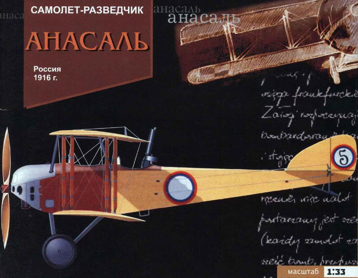
 RECONNAISSANCE AIRCRAFT – “ANASAL”. Scale model 1:33.
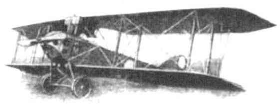
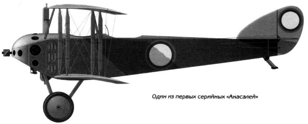
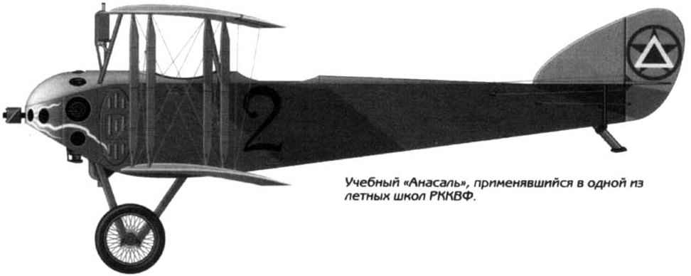
“Anasal” – reconnaissance aircraft developed by aircraft manufacturing factory, founded by Arthur Anatra. “Inasal” (Anatra-DS) on a General view, the contours, size and design nearly the same plane “canadia” (except propulsion), but the scope of the upper wing in different instances varied from of 12.37 to 11.42 m, the length of the plane – from 8.1 to 7.95 m. the Sweep in terms of 4°30 the angle of the box installation wings 4°. The mass flight of the prototype 1130 kg, serial 1164кг.
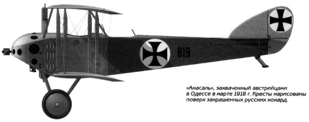
Radiators were placed frontal or tubular (on the sides), the hood had holes around the cylinder heads, bottom the engine was zakoptelova. The sides of the fuselage was covered with plywood along the entire length. Weapons: Vickers machine gun with the synchronizer of the Dean and the gun observer for simple and easy installation pivot.
Speed reached 143 km/h and with screw design “, Grigorashvili” specially made for this plane -150 km/h. Stability and control was good, taking off and landing is simple. In General technical data this aircraft is not inferior aircraft Farman-ZO and German “Albatross” engines at 150-160 HP, the Plane was first tested on July 25, 1916, but the series went only in 1917 there were built 60-70 aircraft used in 1917-1920
 Aircraft performance data aircraft “Anasal “
Wingspan — 11.40
Length — 8.10
Height — 3.36
Wing area, m2 — 37.00
Weight, kg
empty aircraft — 814
normal takeoff — 1164
Engine type -1 PD Salmson
Power, HP -1 x 150
Maximum speed , km/h -144
Cruising speed , km/h — 128
Endurance, h. min — 3.30
The maximum rate of climb, m/min — 182
Practical ceiling — 4300
The crew — 2
Armament: one synchronised 7.7 mm Vickers machine gun and one 7.7-mm Lewis machine gun on a pivot installation.
Assembly instructions
 For model Assembly you need: a sharp knife (scalpel), awl, scissors, thread, ruler, a few pegs, Mylar film (protective glass cockpit), a small sheet of sandpaper medium grain, white glue, UHU glue (for gluing paper to metal, and the manufacture of safety glass), cardboard thickness 0.5 and 1.0 mm, paper clips, wooden toothpicks, knitting needle (for rolling the paper).
The main condition is good quality of the final form of the model is precision and deliberation in the Assembly. Carefully cutting out the parts of the model and intelligently using the glue, you will achieve success. Assembly is easy, if you adhere to the following instructions. Details should be cut strictly on the contour prior to Assembly to give them the necessary form of “dry”.
Carefully review the Assembly diagram and read the instructions. Don’t cut out all the parts at once. Items marked * should be glued onto cardboard, dry them well and then cut. The letter indicates that the indicated portion of the details you need to cut from the inside. Items with letter L after the number is necessary to stick to the left in the direction of flight of the aircraft, and P – on the right. Recommend frames, spars and ribs are glued to cardboard with a thickness of 1 mm and cut at the outside edge, before gluing, lightly processed their face with sandpaper. Place the bend on the outside you can push the blunt side of a knife. The details are well glued together, if they press clothespins. The Assembly sequence may be different from the recommended.
The Assembly of the motor and screw
The Assembly of the motor and screw are manufactured in accordance with Fig.2. The motor and screw are composed of parts 6, 7, 8, 9, 10. The motor shaft are manufactured from toothpicks. The blades of the screw (det. 10) stick a thin paper clip, which passed through det. 9.
Assembly of the fuselage
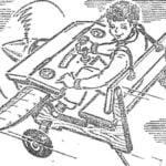
 The fuselage is made of sections in accordance with Fig.1. The Assembly of this fuselage section is not difficult. The frames are glued to 1mm cardboard and kept under pressure. The cabin consists of children.2 (2.1 – 2.13). First frame is assembled from SHP.2A, SHPZ and ST. Collect cubicle with fitted internal parts. Cabin floor (det 2.3) glued on cardboard thickness 0.5 mm. Between the outer (det.2) and inner walls (det. 2.4) cockpit need to paste strips of plain paper (for final Assembly of the cab). The chair is collected from children.2.6 -2.9. Gun – from det. 2.12, 2.13. The control stick is better to collect from toothpicks. After the installation of the seats is glued to the upper part of the cabin (children 2.1 and 2.2) with pre-cut holes. The rest of the section models are assembled in accordance with Fig.1.
The Assembly of the engine compartment
The engine compartment is collected from children. 1A, 1B and 1C. When gluing the hood of the motor (det. 1A) it is better to use plain paper (the hood after drying paint dark paint on the inside). Glue parts 1B and 1 V. After drying it is necessary to cut holes in these locations. Glue parts 1A and 1B. The motor is attached to ШП1А. Glue children.1A. The engine compartment Assembly is attached to ШП1А. After drying, glue the fuselage in accordance with Fig.1.
Assembly of the tail
Empennage is assembled from parts 13, 14, 15, 16, 17, 18. The tail is inserted det. 16. In the rear wing det. 14. In det.4.1 are pasted thread, then they are glued to the fuselage (det.4 and det.5). Glue to the fuselage tail. The threads are glued with a little tension to det.14 and 16 (see Fig.4). Bottom mounted stops wing (det. 18) and the heel (det. 17).
Assembly of the wings
 The lower wing glue from det.11. Guide ribs and glue on cardboard 1 mm thick. the Top wing (det. 12) glue the bottom similarly. The lower wings glued to the fuselage at the marked locations. In the stand (det. 19) glue the segments of the clips (template B). Glue the strut to the lower wing at the marked locations on the wing. The Assembly emphasises the upper wing (det.26) is carried out in accordance with Fig.Z. To the stops glued the upper wings. The Stoics stick to the upper wing at the marked locations. The scheme of the stretch marks shown in Fig.5. Det.22 stick in accordance with Fig.4.
Assemble the landing gear, keeping the corners and glue them into place, according to Fig.4 Chassis consists of children.23, 25, template, 27-33.
Enjoy your work!
Atideo:
The materials to build a model of SPY PLANE – “ANASAL” (download)
Recommend to read
 DESK OF SPEED SPECIALIST
"Wow, beautiful..." — that was the unanimous opinion of the participants about our high-speed cord models. After a short discussion, the boys made a "sentence" is a set of custom-making... HEART ELEKTROLETA
A great many of the problems faces by the Modeler, decided to pursue aviation equipment driven by electric motors. One of the most important and the primary task — the selection...
