Leading athletes of the country are currently doing the fairings arched form of two types: pointed and rounded. Without going into the aerodynamic feasibility and advantage of each type, we consider only the technology of their production.
First— an example of a fairing with a pointed top.
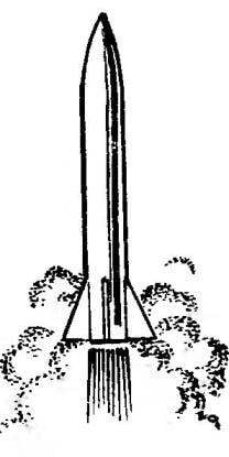
Pointed and rounded fairings.
Frame for it is made of a metal bar on a lathe. It sanded and polished. It is then heated to a temperature of 50°-60°C and covered with wax mastic. The coating is allowed to cool and solidify, so that it was strong.
Fiberglass for the fairing is pre-heated to a temperature of about 300°C in a muffle furnace, with various kinds of waxes, which are impregnated fiberglass, will evaporate, which will then allow you to easily impregnate the fiberglass with epoxy, the polymerisation of which will lead to a significant strength of the product.
A piece of glass, having a slightly large size than required is placed on glass and covered with the resin using a spatula. Giving to soak the resin on the workpiece stack pattern scan cutting head fairing and a scalpel to cut out a necessary part.
Extra pieces of glass removed from the glass. On the edge of the workpiece, put the mandrel. Edge cutting neatly Perlast from the glass on the mandrel and slowly rotating the latter and smoothing out the folds of fiberglass, the winding is carried out.
Winding fiberglass on a mandrel.
The most tricky in that process of gradual untwisting of the top layer of fiberglass, which are not held in the position in which it laid the Modeler. For fixing it I can recommend the following.
First: the top layer of fiberglass to bind to the host thread.
Second: quick warm billet fairing lighted match or over the flame of a spirit lamp to a temperature of the boiling tar and then pinched fingers, giving it the desired shape. Further, the mandrel with the workpiece can be placed in an oven of 50°-60°C to accelerate polymerization of the resin.
The authors successfully used another, and the third way. If you have time, then once in half an hour to fix the fingers in the form of the workpiece of the cone. We recommend you keep the workpiece in close proximity to heat, which will accelerate the polymerization process, and it will be out for 3-4 hours.
After curing of the resin the mandrel is heated, separating the layer of mastic is softened and the preform of the fairing is easily removed from the mandrel. Further, the workpiece is washed with gasoline or turpentine to remove all residual mastic, put back on the mandrel, hides, lacquered (or leave without coverage is at the discretion of the Modeler) and polished. The final operation is the cutting of the end face of the cone.
Leading athletes of Russia — A. Korepin and N. Tsygankov of the Murmansk region using the technology of manufacturing the head fairing in a vacuum. It should be emphasized that the most appropriate form of cone with rounded top cone.
This technology requires the athlete to have certain skills and experience, as well as the presence of a vacuum pump for creating and maintaining the vacuum in the polymerization process of the resin. However, the indisputable advantage of this technology is that the fairing can be fabricated from a single layer of glass, which gives a considerable gain in weight of the finished product.
The manufacture of the fairing using a vacuum pump.
In General terms, this technology consists in the following.
Cutting prepared fabric is impregnated with glass epoxy resin, and carefully wound onto the mandrel. Then a mandrel is inserted inside a balloon (preferably oblong). To hole the ball tightly strapped the hose from the vacuum pump. Then with the help of pump to the end of the polymerization process inside the bulb creates a vacuum. After hardening of the resin, the mandrel with the billet fairing removed from a ball, lightly sanded with fine sandpaper, polished, cut to size and removed from the mandrel. We emphasize once again that produced by this technology, the fairing turns out to be very easy and requires careful handling.
The manufacture of the fairing with the use of molds.
Our story about how to make the head fairing of the rocket Ѕ3А (Ѕ6А) will be incomplete if not to recall another technology — using molds. For the manufacture of the fairing on this method it is necessary to make a matrix and a punch.
As use of the punch mandrel of the head fairing. But first wound on the mandrel two layers of fiberglass on the first technology, process and Polish the surface, but do not remove the cone from the mandrel, and cover it with a layer of mastic “Edelvays”.
The matrix is made from scrap pipe with a diameter of 40-50 mm plug on one end. Preparing epoxy resin with a filler, which is best suited abrasive powder, or, if not, then aluminum powder.
Simple cylindrical mandrel with a longitudinal groove.
The equipment for making the plastic from balsa or foam.
Insert the prepared punch in a section of pipe, fixing his position in the center (at least with clay) and fill the remaining space of the pipe with resin with filler. After polymerization of the resin is heated to form 50°— 60°C, remove the mandrel with the head fairing, removed from his now useless layers of fiberglass. The mold is ready. In the future, the technology is simple. The punch and the matrix is heated, coated with a layer of wax-mastic, the punch wound fiberglass insert it into the matrix and fix it.
At the end of the polymerization process, the mold is heated, remove it from the punch (mandrel) and remove the finished fairing. At a certain skill ready fairing does not require additional treatment and polishing.
There are also alternative ways of making fairings with the use of other materials (polystyrene, plastic), but that’s another topic.
An integral part of the fairing Assembly is an insert bottom for mounting the parachute (band). Inserts typically come in two types, simple and cylindrical with a recess for the tether garter missiles to the recovery system.
Cylindrical mandrel and fabrication of the fairing panels do not cause the Modeler any difficulties. This technology is described earlier on the example of the manufacture of shells and missiles.
Consider the production of fairing panels having the groove-deepening. At first make a cylindrical mandrel. The groove on it can be done on a milling machine or to claw specially sharpened cutter on a lathe, moving the caliper back and forth and feeding the cutter slowly forward. The depth of the groove, usually of 0.8—1 mm.
Next, prepare the frame, fiberglass and produce a winding as described above. Then fiberglass in place of the passage grooves, put the steel wire of suitable cross section and tightly wrapped it all Mylar film (tape the tape).
After polymerization of the resin strip workpiece removed from the mandrel and cut to the desired length. Bonding the bottom cover and setting ring for attaching a rescue system to the fairing should not cause the Modeler difficulty. It is only necessary to remove the wax with mastic surfaces of fiberglass products and careful cleaning for better bonding of the bottom and gluing and fairing inserts.
To simplify the manufacturing technology of the bottom balsa or foam can be recommended to a special device, by which cut the bottoms of the fairing, or manually clamping fixture in the drill press. While it would be good to put under the blank plate of soft material.
Insert fairing with a recess necessary on models, where athletes use relatively thick thread-FAL. Currently, they are increasingly applying a thin thread of heavy-duty Kevlar, which groove is not needed.
THE MANUFACTURE OF STABILIZERS
Leading athletes of the country and the world use stabilizers covered with fiberglass. The technology of their production is. First balsa plate thickness 0.5—0.7 mm (depending on model) cut out into shapes and assemble the package as follows. Heat two sheets of glass. With the help of adhesive tape on each of them attach the Mylar. The Dacron on the first sheet put a piece of fiberglass cloth and coat with epoxy and lay it on the balsa blanks stabilizers. Then covered with a second impregnated ing a piece of glass, a sheet of glass with lavsan and all this in a package compress under pressure or load.
After curing of the resin package is dismantled, the workpiece is cut along the contour of the plates and treated on the edges with a file and sandpaper.
Simpler and more accessible technology for manufacturing the same stabilizers designed Magadan athletes. For,their manufacture requires you to choose the as snap the two plates of the PCB with a thickness of 15-20 mm. Their sizes depend only on the number of regulators that must be manufactured.
The manufacture of stabilizers by using two sheets of glass:
1 — glass; 2 — glass; 3 — foil Mylar; 4 — adhesive tape; 5 — workpiece stabilizers, balsa.
Typically, the PCB has a fairly smooth, sanded surface. Plates should be covered with a separating layer of mastic “Edelvays”, lay on one of them fiberglass, saturate it with epoxy, place the workpiece to collect the package from the second plate on top and compress under pressure. The next day, after drying of the resin, the workpiece is treated in size and ready stabilizers mounted on the model.
The manufacture of stabilizers by two textolite inserts:
1 – plate PCB; 2 — glass; 3 – workpiece stabilizers
From personal experience I can only recommend not to rush to immediately use is made of plate stabilizers, and to give them “stew” for a small press, two or three months, maybe more. The quality will be much higher, as if in a day after curing epoxy resin has a tensile strength of no more than 70-80 percent, then within time it will increase significantly.
A. SHMATOVA, I. SHMATOV, Magadan
Recommend to read THE SUITABILITY OF THE TUBE? The durability of even the most modern electronic devices (EEW) is inferior to semiconductor counterparts. In most cases this is due to the emissivity of the cathode. The matter is... SCHOOL INNOVATION: FROM IDEA TO REALITY Creative finds of young technicians, the successful resolution of their original design objectives our magazine told repeatedly. Examples of research innovation activities of school...