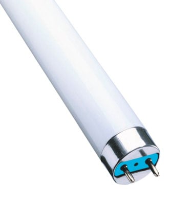
 Fluorescent lighting is much more economical and durable than conventional incandescent lamps. Especially when equipped with modern fluorescent lamps (LDS) with a cap, which fits easily into familiar to all electroputere, and a tubular helical radiator, not exceeding in size the usual tube stellabelle.
In particular, lamps with a domestic brand of LDS ALADIN with a capacity of 12 and 16 watts have a light output approximately 5 times greater than the real possibilities of the former counterparts. Due to the low power called bulb stays cooler during operation, which is important for compliance with fire safety rules. A guaranteed service life reaching 8000 hours, making the LDS “long lived” compared to electric lighting devices, bulbs. Scares sometimes a high cost.
In this context, clear interest in the precursors of products, such as ALADIN — more affordable lamps with traditional cylindrical LDS. Upgrading hardware such enterprising homebrew achieve great results. This is especially true of common devices, power from 18 to 30 watts. The limiting factor is often the lack of chokes (ballast devices) or high voltage, designed for a working voltage of 400 V or more capacitors.
However, undeservedly ignored (and sometimes even thrown in a landfill) bulky, but still quite usable fittings from the obsolete, decommissioned LDS. Although, according to experienced electricians, with the use of such parts, it is possible to modernize the equipment with fluorescent lamps power 18, 20, 27 and 30 W, suitable for domestic use. We only need to understand their name and real opportunities.
Chokes the old type for use as ballast in lighting fixtures with modern LDS
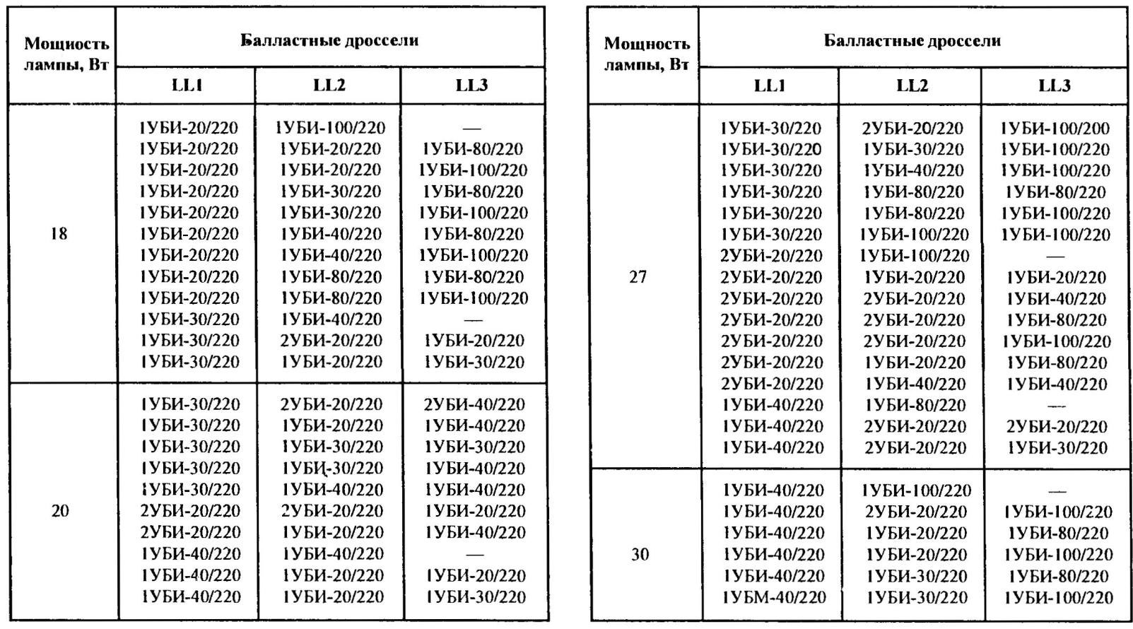
In particular, it is useful to know a transcript of the names of the chokes of old lamps 1УБИ-20/220, 2У6И-30/220 and so on. For example, in 2УБИ-20/220 (new markings — 2И20-A-01-017) figure 2 speaks of the purpose for simultaneous operation with two lamps (a 1 — one); the acronym UBI device inductive ballast; 20 — the nominal power of the connected LDS (in watts); 220V — rated voltage (in volts).
There are also inductors in the name of which is UBI is UBE device is a capacitive ballast. What they are recommended for use in circuits with phase-shifting high-voltage capacitor. This is done in order for the glow of a single flickering bulb of the lamp to shift in time relative to blink the other. But UBI is almost completely replaced by the corresponding UBE, but because in the future everything will be considered only in relation to the first of these types of chokes.
A circuit diagram of a lamp made from junk parts appeared in the solution of practical problems when lighting the desktop there was one 20-watt bulb, and the ballast for it. At the same time was what is called, under the hands of a few 1УБИ 40/220, and other items from the bulky old siteamateur.
So, using two 40-watt choke connected in series (to provide the required power of 20 W) before the LDS to turn on did not, although the starter (80C-220) worked. At the same time, a short circuit of one of UBI (e.g., the second) led to ignition of the pampas, and then the jumper was unnecessary. The outcome of these experiments and became an acceptable scheme. The inductor LL2 in it are not closed manually and with simple automation.
Indeed, fluorescent EL1 is connected via two (LL2) or even three (LL3) UBI (UBE). Due to the selection of the right throttle (see table) it is possible to achieve combustion of the lamp in the nominal mode (with the required capacity). And automatic, performed at relay K1, diode VD1, VD2 and the capacitor C1. required only in order to provide the most favorable mode start fluorescent EL1.
The proposed device operates so that turning on the contacts SA1 SK1 starter short circuit power not only of the intensity of the lamp, but the coil of the relay. Positive half-wave of current pass through the LL1, tungsten filament lamp, diode VD1 and the winding of K1 (at the same time — using ripple smoothing capacitor C1), and LL2 (if necessary, and LL3). The negative half-wave going through the same chokes and diode VD2, bypassing the coil K1.
With warm-up starter SK1 its internal bimetal plates are closed, including relay K1, which your contacts K1.1 block inductor LL2. So the power supply of the filaments of LDS is increased current.
However, as soon as the bimetallic plate starter SK1 cools, they break the chain of supply, not only yarn, but also the relay coil K1. The Contacts K1.1 opens, connecting consistently LL2 (and LL3). At the time of separation of the inner strips starter SK1 on the winding of the inductor LL1 is due to EMF of self-inductance high-voltage pulse, igniting the fluorescent lamp. If the first ignition attempt fails, the device automatically repeats (usually two or three times), providing fire EL1.
The ignition of LDS leads to the fact that the starter SK1 can not (because of the lowered to 80-100 In voltage on the burning of LDS) to work, so the automation has no effect on the combustion regime.
The duration of the process of ignition of the cold lamp in this lamp is about 1 s. it was Experimentally established that it is quite efficient LDS not only with one blown filament, but both. However, if the time of ignition of the fluorescent lamp rises to 35 C.
Failed filament must be closed directly in most LDS. To do this, simply fold the foil strip in width of 15-20 mm and wear on the base where the filament is burned out. The foil needs to provide electrical contact not only with the findings of LDS, but also with the metal cap.
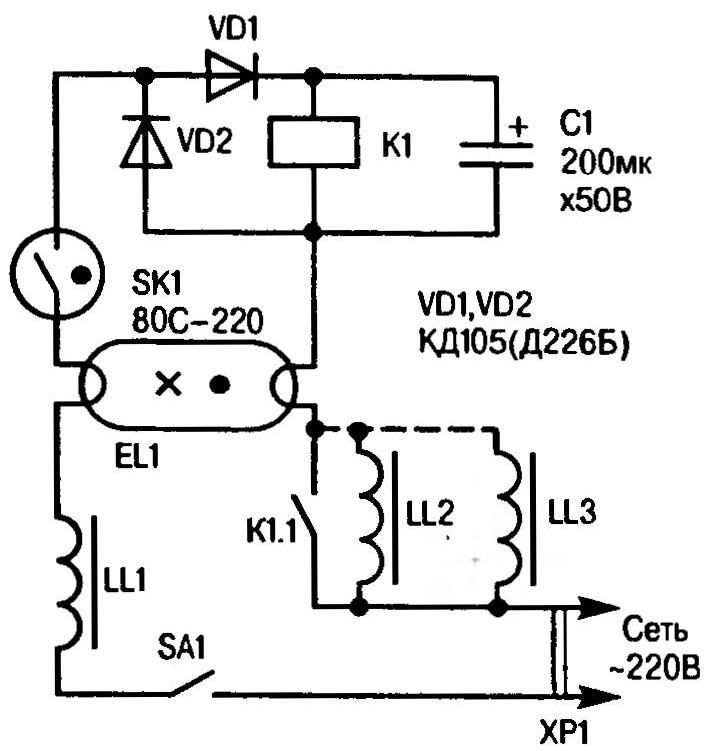
A circuit diagram of a modified lamp with the use of pescarului devices from obsolete siteamateur
SK1 starter is a valid use of normally open switch buttons. Then the switch SA1 can be replaced the second but normally closed button. First contacts in this case will serve to enable LDS and the second to turn it off. Can do without the relay K1 capacitor C1 and the diode VD2 and diode VD1 to replace ordinary jumper. However, this requires closing the button with two contact pairs, one of which needs to be separated a little earlier than the other. And again. The contacts of the first pair are designed to short-circuit the lamp EL1, and the second findings of the inductor LL2 (and LL-H). Turn off the lamp, and in this embodiment the release button.
Switching inductors LL2, and LL-3 relay contacts may be accompanied by heavy sparking. Why do K1.1 must have high erosion resistance. The best option here is to use a relay of a sound signal of cars VAZ, AZLK, ZAZ or (e.g., relay 111.3747, 112.3747, 113.3747 and their analogues). Winding this 85-lot relay with a trigger voltage of no more than 8 may be labeled 85 and 86 and closing relay contacts 30 and 87.
Diodes VD1, VD2—Д226Б or КД105. As the capacitor C1 IS quite acceptable-2 or other oxide, designed for a rated voltage of not less than 15 V.
V. BANNIKOV
Recommend to read
 V8-ENGINE FROM SCRATCH
V8-motor built in 1992 from scratch. All parts are constructed Soren Pedersen. Ø21мм pistons, hub 20 mm runs on ordinary gasoline with 1% oil. Video: THE AIRBOAT OFFENSIVE AND MINIATURE
...Already left behind a crucial period of the war. Vienna, like many Austrian cities, a lot of bitter've seen over these difficult years. Destroyed the magnificent palaces and...
