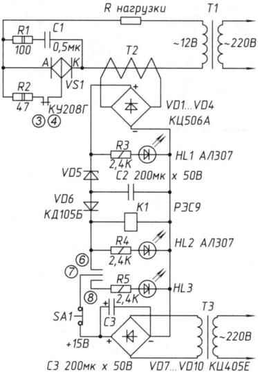
 Circuit of electronic fuse alternating current, represented in the figure, protects the circuit in which the output is regulated by the triac (or just the triac operates in the mode “connect – disconnect”) by removal of the control signals when current exceeding the specified value (emergency operation).
If the current exceeds the limit value, the contacts 3 and 4 (normally closed) break the control circuit of the triac. When the current in the load circuit does not exceed the set level, the relay K1 is de-energized, glow led NL3 (green) and led НL1. When the current exceeds a predetermined level, the Zener diode VD5 gives the command and relay K1 is triggered sambodha-is being developed via normally open contacts 6, 7.
Contacts 3, 4 open: contacts 7, 8 is also open. NL3 (green) ceases to Shine and lights up red НL2. After eliminating the cause of abnormal operation in the load circuit button is pressed ЅА1 and the protection circuit is again ready to work.
When the triac control current in the load is controlled by a pulse transformer, the contacts 3, 4 are connected in the gap of the primary winding of the transformer. Naturally, the presented fuse works in any AC circuit, even if she is not regulated by a power triac.
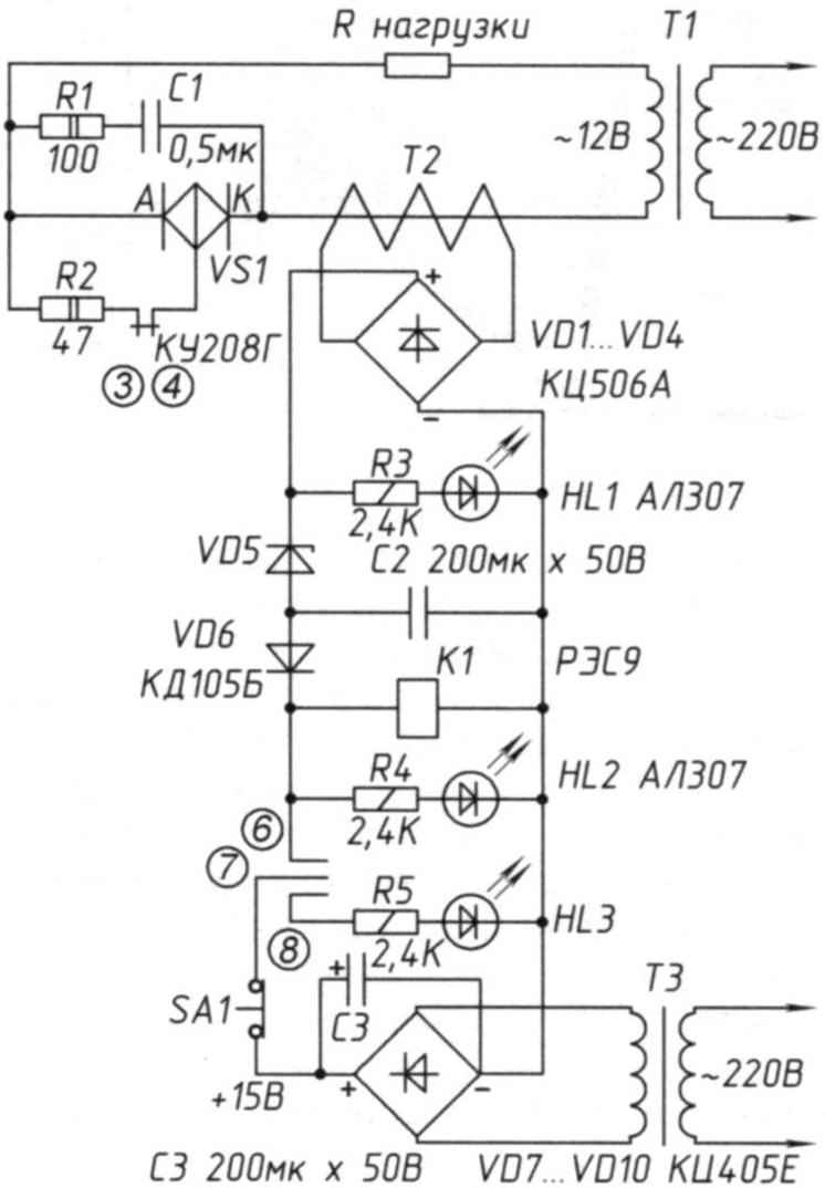
To configure the scheme used to fuse the transformer T1 of the type TPP-287-220-50K. Connecting the load resistors of PEV value from a fraction to a few Ohms is convenient and safe to different currents. As of the current transformer T2 is used under the hand of a small transformer. Leaving him only the primary winding (the coils 2740, PETV-2 diameter of 0.125), the secondary winding removed and wound with 8 turns of wire mgshv-2,5 (the numbers indicate the wire diameter in mm). These 8 turn and made a winding of the current transformer. Its power is a few watts (iron Ш20х20). The transformer TK is the same as T2, but the secondary winding gives 15 In left to power the relay K1, when it smoothfaced. Button ЅА1 — type KM-1 (used its contacts 1 — 3). LEDs НL1, НL2 — АЛ307 (either the last letter) red. NL3 — green (type unknown to me — erased markings).
Chain R1С1 provides comfort to the triac VS1 during outages-inclusions. C1 capacitor — type МБГ4-1 (0.5 µm x 250). Relay K1 — type RES9 RS4.524.200 (15 V, trigger current of 30 mA, the releasing current of 6 mA, u=2,58). Capacitors C2, NW — type K50-12 (200 µm x 50 In).
Besides, who wants to use the proposed idea of the fuse, you must use the literature [1].
S. LEVCHENKO, St. P etersburg
Literature
1. R. Thomas. Compact direct current relay. Radio No. 1, 1973 (p. 56.,.58, 61).
Recommend to read
 PANTRY FOR HARVEST
The development of the garden associations, the construction of houses and cottages caused an increased interest in structures designed to preserve the generous gifts of autumn. In... THE SHIP ON THE PILLOW
This is a hovercraft I built for several years. Engine - from VAZ-2108 with a capacity of 74 HP, Case - fiberglass, fiberglass epoxy resin, is made of the type "sandwich" with the...
