
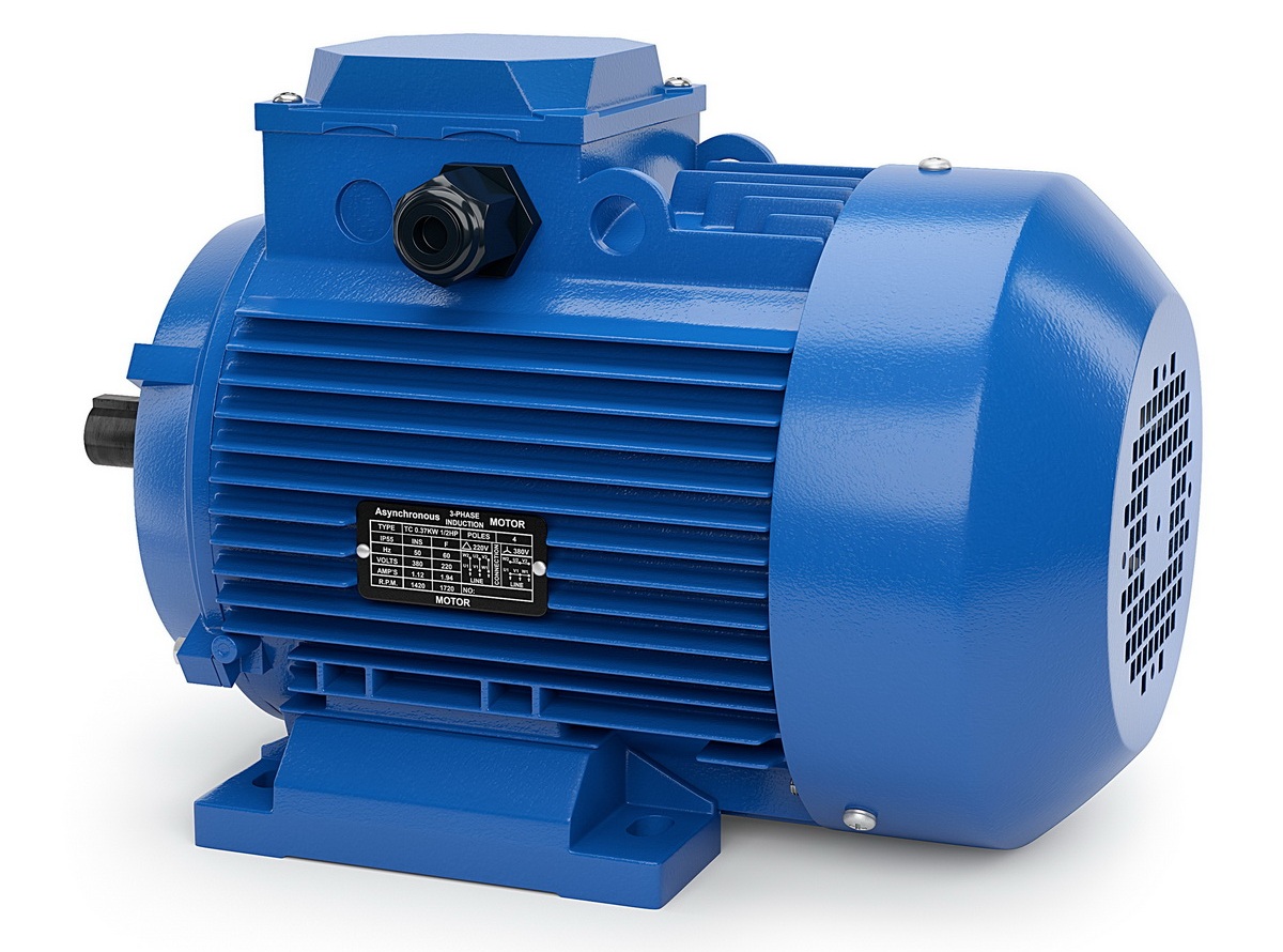
 “For the treatment of infield has decided to replace the tiller internal combustion engine electric. Already got polutoraterabaytny the motor. But it is three phase. How to connect to the network, where only one phase and “my best”?
 N. PARIN, Kursk oblast“
“I heard that three-phase electric motors in the home network the homebrew use phase-shifting (but not electrolytic) capacitors of large capacitance. Is this true?
V. CHUPIKOV, Dnipropetrovsk“
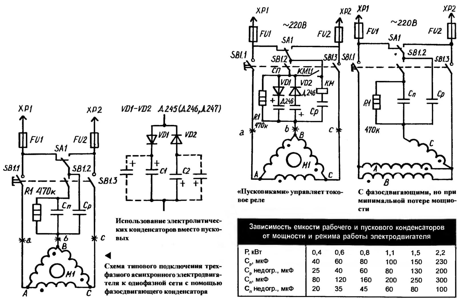
Among the various ways of including three-phase asynchronous motors in single-phase network is probably the most simple and the most well known using capacitor called (because they performed in this case functions) of the phase shifter. In this case we have to put up with the inevitable loss of power. For electrically connecting the windings “triangle” even in the ideal case it will amount to 40-50 percent of its nominal specified in the data sheet. In addition, depending on rpm, gaining engine capacity from phase-shifting capacitor must change.
Last difficult to implement in practice. Usually satisfied with two-stage control scheme, when the inclusion is carried out using a starting capacitor of large capacitance (due to the occurrence of significant currents at start), followed by its replacement to work with the smaller denomination.
When connecting windings “triangle” the capacity of the working capacitor CP is determined by the formula:
MS =4800 I/U,
where U is voltage, V; I — current, [a], which can be measured by ammeter or calculated using known mathematical expression:
I = P/1,73 Uηcosφ,
where, in addition to the above notation, φ — efficiency, cosφ — power factor.
As for the capacity of the starting capacitor, when a considerable load on the shaft, it is selected in 2-2,5 times greater than the value of the operating capacitor. Well, if the electric motor will be operated in fully loaded mode, both containers should be reduced (see table). Capacitors it is better to use the type of MGB and the like with paper dielectric (MBGP, MBGC), and the permissible stresses to which they are to be calculated at one and a half times the supply voltage.
Typical wiring diagram for start and run three phase asynchronous electric motor with such capacitors usually contain a special shunt is a resistor with a resistance of 200-500 ohms, through which will drain the charge from the disconnected “Boskovice”. As the SA1 toggle —switch of the type TB1-4. Is it the switch reverse. SB1 — button starter PNWS-10УХЛ2 (for example, from the washing machine). When this button is pressed, the motor is connected to the network through a parallel connected starting and working condensers. After M1 is very quickly gaining momentum, SB1 released. Contacts SB1.2 are open but the rest remains closed until, until there is a need to stop the engine—it is the structural feature PNWS-10УХЛ2. That is, in the operating mode SP is disconnected from the CP, which was required to achieve.
Sometimes you have to face the fact that the SB1.2 when you let the button won’t come off. Well, it is necessary to intervene to make everything work properly. For example, to put under the contact washer.
Harder if you are not able to purchase paper capacitors for the circuit start-up. From bolsaescola, say, get could only electrolytic. To use such a capacitor as a “pustovitov” there is a special circuit with semiconductor diodes D245—Д247 and the like that can withstand a reverse voltage of at least 300 V and direct current of 10 A. When working with engine of high power diode pair and set in each of the arms on the heat sinks. Otherwise threatens the breakdown of semiconductor devices. Then, using oxide capacitors will flow AC current, and “electrolytes” can overheat and rupture.
For the same reasons, by the way, do not use electrolytic capacitors as workers. Because the currents there occur considerable, and even a long time. Not every “electrolyte” is able to withstand such a difficult regime.
If the motor will have to work under high dynamic loads on the shaft, it is possible to recommend a scheme where the starting capacitors controls the current relay. Reacting to the changing current in the windings (i.e., the result of the dynamic loads experienced by the rotor shaft), the relay automatically enables or disables “Pyskowice”, making the phase-shifting capacity, respectively, greater or lesser. Business will only benefit from this.
Pick the right value of the capacity paper and electrolytic capacitors the easiest way, achieving equality of the currents at points a, b, C. the latter is possible with optimal load on the motor shaft.
Other prevailing wiring diagrams three phase motor to single phase not to mention an original solution to reduce power losses up to 25 percent. And because the winding A and is included In antiphase. And for a full 220 V. the Voltage of the rotation is determined by the inclusion of winding C. To not make a mess with the inclusion of the windings, their phasing are shown by dots.
Fans to do everything thoroughly, to give technology of the maximum return will likely be interested in the scheme with registerno-inductive-capacitive transducer single-phase 220 V three-phase. Because it allows you to give the engine the opportunity to work with shear stresses of about 120° and currents in phases of up to 4 A.
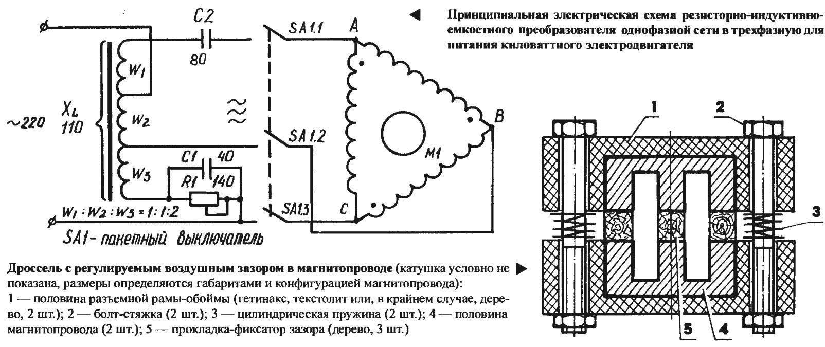
The Converter uses capacitors KBG (MBGO, MBGP, MBG-4), 700-watt resistor and inductor, the magnetic core with air gap. (The resistor of Nickel-chromium wire with a diameter of 1.3—1.5 mm, are wound on a porcelain rod or tube with a diameter of 20-30 mm. on the Movable coil bracket-to-contact with the fixing allows to obtain the required resistance to ensure reliable operation of the engine some power.) Is the inductance of the choke better, apparently, to indicate its inductive reactance, which is easier to define and monitor against readings of voltmeter and ammeter. So, at frequency of 50 Hz it should be set to 110 Ohms (active resistance of the winding can be neglected).
In fact, the form and type of steel of the magnetic circuit can be arbitrary. Most importantly, to provide an air gap, and hence the ability to change the inductive reactance of the inductor. Quite suitable, for example, hardware from power transformers 270-450 watts.
If the magnetic core cross-section mm2 16 to 18 for the inductor wound only 600-700 turns of wire with a diameter of 1.3—1.5 mm. Coil this trial. Gathering her choke with an approximate gap include inductance in the network to measure the reactance of the prototype of the future details. Then figure out how many turns you need to add (or subtract) to get the required XL.
Found thus the total number of turns divided into three parts in the ratio 1:1:2. These data are used in the winding of this choke-coil, performed on the three-section frame, the size of which are determined by the dimensions and the specific configuration chosen for the transducer magnetic circuit. If, for example, found through a test coil number of turns is equal to 600, the “real” working the throttle w1 = w2 = 150, w3 = 300.
It is useful, I think, to recall that the above data on the Converter to three-phase motor 1 kW. Recalculation of parameters on a different power should be by the formulas:
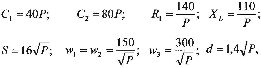
where C1 is the capacitance of the capacitor of the same name, UF; C2 is the capacitance of the second (the scheme) of the capacitor, UF; R— power Converter, kW; R1 is the resistance of the resistor in Ohms; XL is the reactance of the inductor. Ohms; S — cross section of magnetic core, mm2; d — diameter of the wire for winding the inductor, mm; w1, w2, w3 is the number of turns in the respective section.
And a few comments on the specifics of the design of the inverter and use its parts. The resistor, of course, must be cooled, at least a convection flow of air. At the same time, it is necessary to provide protection from accidental contact with conductive connections. Well, the choke is desirable to do so, so it was easy to change the gap in the magnetic circuit (therefore, to adjust the inductive reactance of the Converter). For example, using wooden sticks-strips firmly fixed by straps of a screw thread.
The Converter is reassembled and placed in a metal case, the dimensions of which are determined by the dimensions of parts and assemblies design. All wiring is mounted.
A. KUKHARENKO, Grodno, Republic of Belarus
Recommend to read
 DIRTY PACKAGE
Want it or not, but when painting the walls or ceiling a paint roller, some part of the paint inevitably gets on your hands. Will save you from this simple device - a plastic bag, fixed...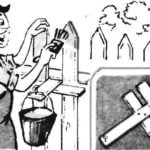 THE BRACKET FOR THE BUCKET
To facilitate the painting of the fence will help the simplest bracket to the bucket.
