AND SHARPENING, AND DRILLING, AND MILL

Universal woodworking machine in the embodiment horizontalscrollmode machineTo create a lathe-boring woodworking machine me prompted memories of school days when in the classroom I received the first skills of work on a lathe — lesson interesting and exciting. Since then, as they say, much water has flowed, but the desire to do of wood pieces of furniture with a beautiful chiseled details is preserved, but the necessary lathe I had. And I decided to do it, adapting to the bed of the other machine, consisting of a “circular saw” and electrofunk (see “M-K” № 1 ‘2011), thus obtaining woodworking mini-complex.


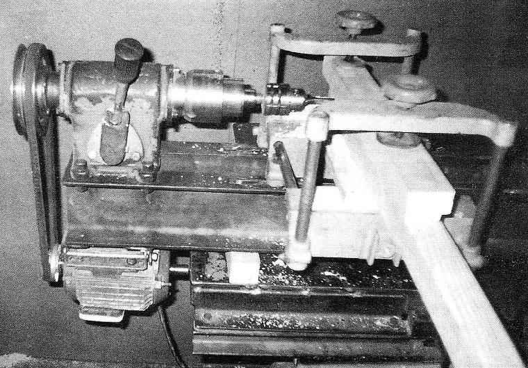
The process of designing and manufacturing lathe were occupied not less interesting than megachilinae details on it, because it wanted to build multipurpose transformable machine, which could perform several operations. I think that I in some way failed because the machine can carry out turning, drilling, slotting and grinding operations. Various additional devices significantly extends the functionality of the machine.

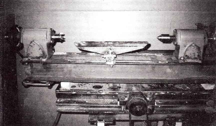
Important advantage of the machine is that it is relatively simple in design, as its main components: front and rear headstock, the drilling head is constructed on the basis of the same body of the worm gears, and therefore relatively difficult to manufacture (although some parts had to be ordered turners professional), reliable and easy to use.

Multi-purpose woodworking machine

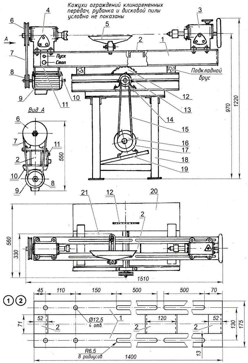
Multifunction wood cutting machine:

1—the guide of the frame (channel No. 12. 2); 2—cross member of the frame (channel No. 12. 3). 3 — tailstock with quill; 4 — front headstock; 5—handrest: 6—driven pulley belt transmission: 7 — V-belt; 8 — drive pulley V-belt transmission; 9—the electric motor (3-phase, N=0.7 kW, 2850 rpm); 10—a bracket of fastening of the engine to the frame (steel sheet s, 2); 11 —control; 12—disc saw; 13—rotor plane; 14—driven pulley belt transmission “circular saw”: 15 — V-belt “circular saw”: a 16—drive pulley V-belt transmission “conveyers”; 17—motor “buzz-saws”; 18—frame “conveyers”; 19—Playground of the motor 20 is a table of the circular saw; a 21 —table planer

Structurally, the machine consists of frame, electric drive with V-belt drive, front and rear attendants, boring side of the head. The attentive reader will notice that this is not mentioned in the frame (or base) of the machine, and the basis for lathe serve as a frame table and other woodworking machines — circular saws, combined with the plane. This constructive solution, maybe someone will cause disapproval and even censure, but I think that it is very rational: saves space, materials. Frame is installed on pre-laid on the table of the planer with wood blocks and attached thereto by clamps.

Multi-purpose woodworking machine

Multifunction woodworking machine

The frame is made of a pair of segments (with a length of 1400 mm) of the rolling channel number 12 (wall height is 120 mm, flange width — 52 mm) — guides connected (welded) in three places (on the edges and in the middle) short segments of the same channel. In the upper shelves of almost the entire length (excluding the left edge) is made through the longitudinal guide grooves, which move the tailstock, armrest or backrest. In the left edge along the axis of the grooves drilled holes for permanent mounting headstock. About the middle of the length of the frame in the grooves left by the jumper, through which these fixtures are rearranged. This creates some inconvenience (though this happens infrequently), but retains the stiffness of the guides. The grooves are cut with a angle grinder, pre-drilled at their ends in the ground jumper the appropriate holes with a drill. The final finishing of the grooves performed by grinding the edges of the rails, controlling the quality of work ease of movement of the tailstock.

Headstock is mounted on the left edge of the frame and is attached to it by bolts. Itself grandmother made on the basis of a cast iron case worm gearbox, inside which is installed a worm gear shaft-spindle, revolving in bearings 305. Axial load takes on the thrust bearing 8105. On the right end of the spindle is mounted face capture — the Trident centre. It serves for fixing and rotation of the processed wooden piece. Instead of grabbing the spindle to secure the flange, and it is abrasive, grinding or polishing lap. They are needed for sharpening and grinding cutting tools or finish treatment (finishing) wood products. The flange can be set and dividing the circle, which will allow for the lathe and milling. On the other (left) end of the spindle is mounted the driven pulley belt transmission.

Front (spindle) headstock

Front (spindle) headstock:

1 —housing; 2—cover housing; 3—bearing 305 (2); 4—bearing cap 305; the 5 — Trident; 6 (special screw M10); 7—dowel (2 PCs); 8—M8 screw (12 PCs); 9—shaft (steel, round 32); 10—thrust bearing 8105; 11 —a cover of bearings 305 and 8105; 12—pulley; 13—washer (2); 14—emery wheel; 15—cheek abrasive wheel (steel, 2 pieces); 16—nut M18; 17—remote sleeve

The drive is three-phase (supply voltage 380 V) motor power 0.7 kW revolutions of 2850 per minute. First motor mounted on the console, pivotally connected with the frame ground. But for the sake of compactness and ease later hung it under the front headstock on the frame by means of brackets. Mounted on the motor shaft drive pulley along with the driven reduces the number of revolutions of the workpiece up to 1600 per minute (which is sufficient and even desirable) with simultaneous corresponding increase in torque.

The tailstock is mounted on the right end of the machine bed. It is intended primarily for maintaining the cantilever end of workpieces of different length using rotating centre, but it is possible to install an additional tool (e.g. a drill bit for receiving axial holes or countersink bit). In this regard, the tailstock has the ability to move along the guide rails and fixed in position on the frame clamps with screws M12x1,5. She, like the headstock, is made in the body from the worm gear, but its design is as close to a commercial product. First, it is equipped with a retractable tailstock with a rotating center. The extension of the quill is carried by the flywheel fixed on the rear end of the lead screw. Secondly, the tailstock is equipped with mechanisms of fixation: this can be done by a clamp, braking spindle feed quill with the handwheel located on the gear housing from the top, or sitopornogratis MB screw, screwed into the guide sleeve (bottom of it). But the main purpose of this screw is not to allow the quill to turn, and move only in the longitudinal direction along the axis. To do this, in most of the quill is made a longitudinal groove, into which enters the screw end. The departure of the quill is up to 85 mm. the Bearings of the rotating center planted in your body “hot”, without any additional fastening. And that’s enough, that was confirmed quite a long (and most importantly, intensive) operation of the machine.

Tailstock with the tailstock and rotating center

Tailstock with tailstock and revolving centre:

1 — tailstock body (worm gear); 2—bearing cap; 3—flywheel (from a standard worm gear); 4—the screw of fastening of a flywheel to the driving screw; 5—a key; 6 — M8 screw mount the bearing cover to the housing (3). 7 bearing 305; 8—clamp locking screw; 9—handwheel locking screw; 10—rod clamp; 11 —axis of the clamp; 12 — fallopian М20х2 nut; 13 — quill; 14—screw М20х2 (regular worm gear, modified); 15—fastening screw M8 guide bushing of the movable sleeve (3 pieces); 16—pin; 17—a tip of the quill; 18—thrust bearing 8103; 19—bearing s103; 20—radial bearing 202,2 PCs); 21 —thrust washer; 22—; 23 —the bearing housing; 24—guide screw-stopper of the movable sleeve (screw M6)


Tailstock with the tailstock and rotating centerHole of the worm gear housings are closed lids.

The armrest is designed to maintain the cutting tool during machining. It consists of three parts: cross rails with a longitudinal slot, the composite strut and the base plate. The last (major) detail is made of a slightly flattened angle of area No. 5 (50×50 mm). The handrest is near from the master guide between the front and rear head and secured it with the bolt. It can be moved between along the rail. The design includes the possibility of adjustment in height (by varying the angle between the component parts of the rack), and the distance to the workpiece (transverse movement in the slots of the rack). This fixture is to describe in detail will not, because everyone does it.

Universal woodworking machine in the embodiment verticalinstabile machineThe drill attachment is made on the same frame, and lathe. It consists of the drilling head and the working table. The head is mounted in place of the headstock and the table in place of the armrest. To work as a horizontal drilling machine bed is fitted next to the “buzz-saws” in a vertical position and fastened to it with clamps. As additional support for the drilling console, you can use the handwheel tailstock quill.

Drilling head — the most difficult (and therefore most interesting in terms of design) the site of the machine. Casing drilling heads was all the same housing a worm gear, that the front (or rear) of the headstock. But the internal device is a little more complicated. It constructively combines the mechanisms of both the front and rear headstock: slotted shaft with a drive pulley and a splined coupling with quill. Outside attached to the body using three M8 screws (head S10) of the quill sleeve with an inner diameter of 62 mm. It is the guide of the movable sleeve, the axial stroke of approximately 100 mm. And that the tailstock was made only oscillating movement along the axis, not turning on its outer surface a longitudinal groove, which runs profiled (section of groove) the end of the limiter screw M5, screwed from above into the sleeve of the quill.

A balancing system or a spring lifting tool in an unusable state (when using the drill set-up option vertical drilling machine) is not immediately set, and now have adapted and are doing just fine without her.

Drilling head

Drilling head:

1—case (worm gear); 2—radial ball bearing 206; 3—thrust ball bearing 8106; 4—a remote washer; 5—pulley; 6 — splined bushing; 7—splined shaft; 8—a nut М30х1,5 of fastening of a pulley; 9 — a cover of bearings; 10 — screw M8 fastening the bearing caps to the housing (3). 11—restrictive washer; 12—thrust ring (bronze); 13—coupling; 14—handwheel spindle (standard gear); 15—screw M8 mounting sleeve of the movable sleeve to the housing (3). 16—bearing 304к; 17—pinol; 18—casing of the quill; 19—spindle beneath the cone No. 2; 20—guide screw-stopper of the movable sleeve (screw M6); 21 —bearing 205; 22—tool Chuck with taper No. 2; 23 — a shaft drive pin bushings; 24—305 bearing (2 PCs); 25—bearing cap (2 PCs.); 26—the driver sleeve; 27—the leash (2); 28—control knob to the feed of the tool; 29—screw M6 interaction of lead with ring: 30—M6 screws attaching the bearing cover to the housing (3). 31 —stopper bushing drive pin on the shaft (screw M6, 2 PCs.); 32—stopper lever-feed control of the tool on the shaft drive pin bushings

Desktop vertical drilling machine is so simple that its design is clear even from the photo, so the drawing does not cite.

S. yakishev in a, p. Yeniseisk, Krasnoyarsk Krai

Recommend to read

  • CONVERTIBLE “TOURIST”CONVERTIBLE “TOURIST”
    Homemade car "Tourist", designed by V. Golovchenko from the city of Tashkent, has good proportions, clean lines. Great help, the author notes, had a publication in our magazine about the...
  • IN SUMMER THE AIRCAR IN THE WINTER — SNOWMOBILEIN SUMMER THE AIRCAR IN THE WINTER — SNOWMOBILE
    Built unusual car A. Kulakov from the village Kutulik Irkutsk region. Her body is aluminum; the front suspension from a cargo scooter "Vyatka", the rear of the scooter "Tula 200". A used...