 In the “Modeller-designer” has repeatedly published materials on woodworking machines-“circular saw” circular saw and planer, so necessary for the house masters. On this publication have done for a similar machine and I. But when I did, I realized that not everything in it is fine with me. In particular, the mechanism of lifting-lowering of the table. And the device is called the mechanism was only possible with the big stretch. The table was mounted on four studs-the uprights and vertical movement required to turn is to roll as many as eight nuts. And to set the plane of the table parallel to the axis of the plane (and saws) had “by eye”. In the end decided to make another table with more “advanced” mechanism (table) of lifting-lowering.
The base of the lifting table serves as a frame. Its dimensions agree with the dimensions of the top frame saws.
Frame is made of steel anyway-shelf corner № 6,3 and is dismountable: it cross members (I have them with a length of 425 mm) attached to a longitudinal (length — 560 mm) screws M6. But without welding not done. At the ends of the longitudinal members are welded end plates cut from 5-mm steel and has been cut on the inner profile of the area. The plates are made with three holes with a diameter of 6.2 mm, and the vertical shelves of the crossbars corresponding threaded holes M6, through which screws M6 items and sealed. In the longitudinal elements at a distance of 60 mm from the ends and 15 mm from the upper edge of the vertical shelf drilled two holes with a diameter of 18 mm for bearing sleeves of the shafts.
Bearing sleeves carved from strips of half-inch water pipes inserted into the holes and welded to the corners. But to make it better simultaneously with the mounting of the shafts is then easier to observe the alignment bushings and provide easy bends in them shafts, for which it is useful to apply the rubbing surfaces grease.
The shafts (two of them) are solid steel rods of length 430 mm, machined from a cylindrical rod with a diameter of 18 mm. One end of each shaft is squared under a square of side 12 mm is it fitted with a lever, which is lifting and lowering of the table.
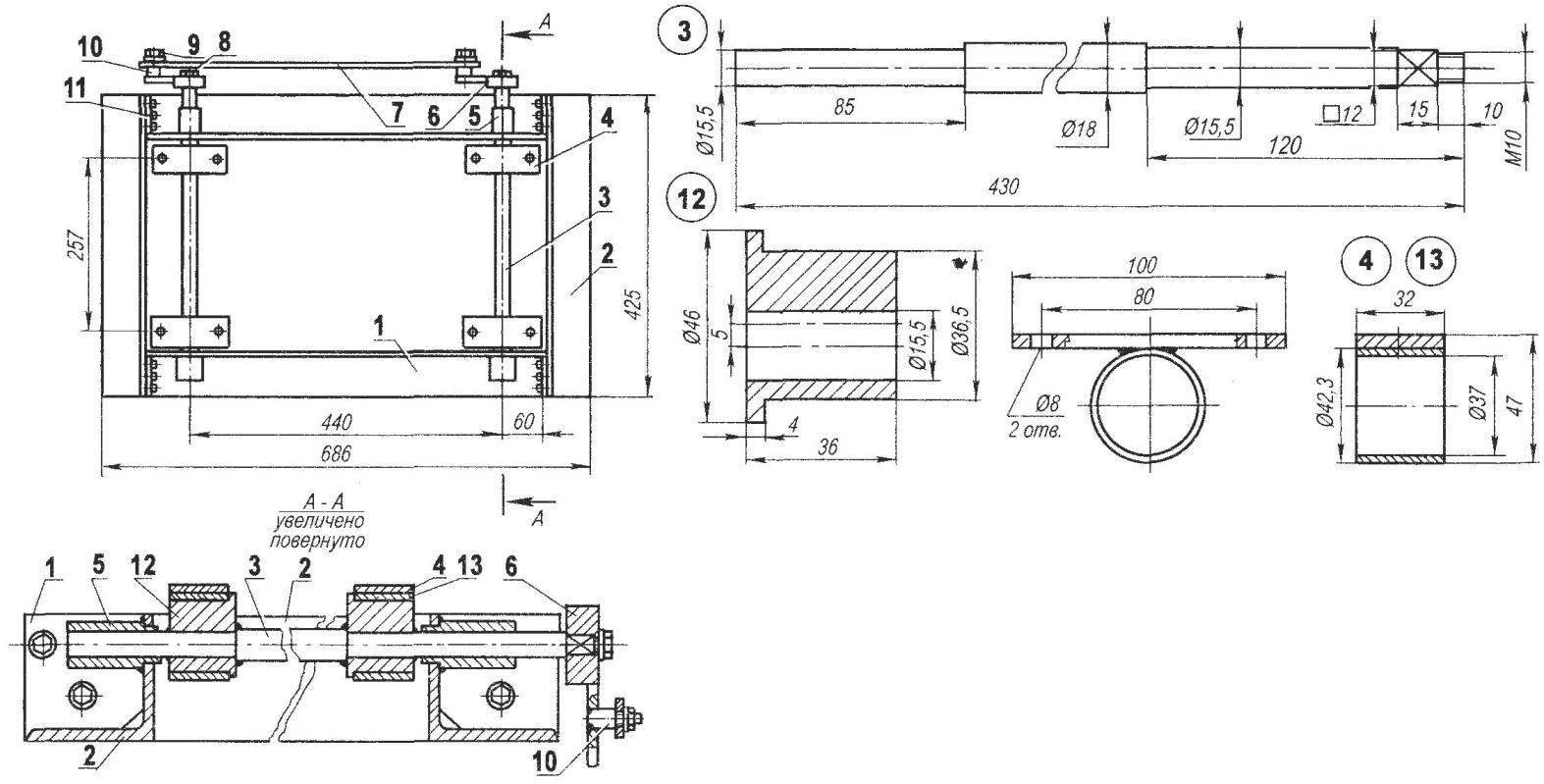
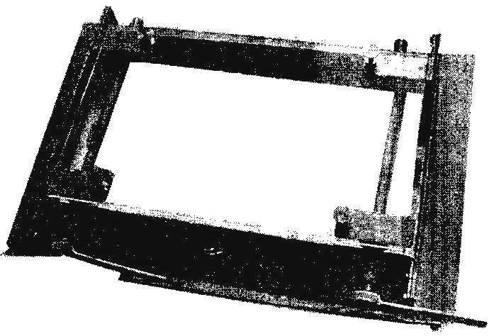
Desk woodworking machine with its fast mechanism of lifting-lowering:
1, the longitudinal element of the frame with the end plate (area 63×63, 2); 2 — transverse element of the frame (area 63х63, 2); 3 — shaft (steel, round 18, 2); 4 — bracket working table ( steel, sheet s5.4 PCs); 5 — bearing shaft sleeve (tube 1/2″, 4 pieces): 6 — arm (clutch with handle, 2); 7 — thrust (steel strip 3×20): 8 — mount the clutch lever on the shaft (nut M10 2 PCs); 9 — mount the thrust axis of the lever (nut M8 2 PCs); 10 — axis thrust (steel, circle 8, 2); 11 – the connecting elements of the frame (bolt M6-12 PCs); 12 — eccentric bushing (round 46, 4 pieces); 13 — yoke eccentric bushings (4 PCs)
The lever is a handle welded to a cylindrical hub with a Central (axial) square hole corresponding to the square end of the shaft.
Levers, and shafts, also two. For uniform table lifting levers are connected by a traction, made of steel strips section mm. 3×20 Pull freely planted on the axis, welded to the levers.
The main elements of a raising-lowering table, are eccentric. They are machined from steel round rod with a diameter of 46 mm. Holes in each of them with the eccentricity of 5 mm were also drilled right on a lathe. To do this, when clamping parts in the cartridge under one of the Cams was placed a steel plate with a thickness of 10 mm. travel of table (vertical movement) after that was also 10 mm.
Eccentric onto the shaft and fixed to it by welding. Before welding you need to make sure that all Cams are pointing in the same direction at the same position of the levers.
But before that is put on the eccentric sleeve with welded thereto brackets for fixing the table. In the photo the table for clarity of the whole structure is made of Plexiglas and attached to the cradle by screws with the big (and not hidden) heads. In the nature of the table itself is large and its edges extend beyond the frame (but only a sheet of Plexiglas were available).
Frame lifting table is mounted on upper frame members of the machine, and the two structures are bolted together by simultaneously drilled the appropriate holes.
P. SPEAR, the city of Beloretsk, Bashkortostan
Recommend to read
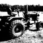 AS FOR THE VILLAGE WITHOUT A TRACTOR?
(Continued. Beginning in № 8'02) FRONT AXLE — wheels from UAZ. Balancer axle is made of steel tube section 80x80x6 mm long, the ends of which with longitudinal and transverse...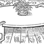 IN A MODERN STYLE
Round tables are in fashion: buying new furniture, they are often sent to a landfill. However, this is hardly justified. To verify this, just look at the figure — four boards plus round...
