MEET: I — ROBOT “ORION”

MEET: I AM A ROBOT 
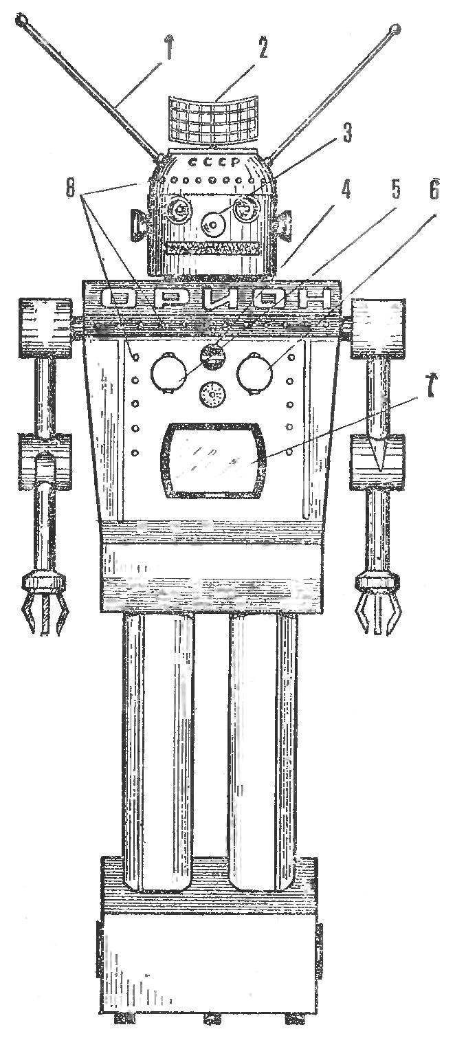
Perhaps in the near future when the new spacecraft will go to the moon, Venus or Mars in the Arsenal of the astronauts will be robots who will come first to the planet’s surface to conduct scientific researches, to perform simple welding and Assembly work. So I decided the guys from the mug space simulation Sumy city station of young technicians and build a similar robot with their hands.

 
“Orion” (so called his brainchild of its creators) can perform a number of actions inherent in a living organism. In the darkness he is sleeping, when the lights are “awakens” and goes straight to the PA light. The robot can move forward, backward, right and left. As a man, he comes and takes a variety of items, talking, turning head to the sides.
 
Cyber simultaneously a researcher and a welder by profession. Signals from the locator and the sensor radiation hazards, processes, miniature computers. The collected information displays installed in the trunk video device.
 
The welding robot performs the following way. Robotic arm takes a special electrode at the end of which is thermite match with elektrozapalom. High temperature thermite matches (1500° C) allows to cut metal plate up to 3 mm thickness.
 
Fig. 1. The appearance of the robot
 
Fig. 1. Appearance of robot:
 
1 — antenna, 2 — radar, 3 – “focus on light”, the 4 — sensor to detect radiation, 5 — microphone, 6 — siren 7 — teleinformation, 8 — lamp computers.

 
At the final of the X all-Union competition “Space” the robot “Orion” took first place in the section “Promotion space”.
 
STRUCTURAL SCHEME. Control a robot with a remote control, which is a row of toggle switches, but some operations are performed automatically (Fig. 2).
 
Include switch Power controller is ready for operation. Now, manipulating separate switches, give the robot instructions. Toggle “Locator” includes motor antenna rotation and the flip of a switch with the tag “computer” is enough to cyber started “thinking”: activates the motor of the interrupter simulating “computer”, and alternately lights the bulbs on the front of the robot, show it “thinking”.
The robot motion is performed with two reversible motors. For their management are two two-pole switch, position contacts of which depend on the direction of rotation of the motors.
 
Mechanical hand-manipulator is equipped with three electric motors, the commands are received also from the control panel. The manipulator can be rotated around the axis by 270° in the “shoulder joint” and 90° “elbow”. The locking mechanism is connected to the engine, the rotation of which enables to compress and decompress the “fingers” of the manipulator.
 
Fig. 2. A block diagram of the robot
 
Fig. 2. A block diagram of the robot:
 
1 — radar, 2 — communication unit 3 — the simulator computer 4 — video, 5 — welding 6 — control mechanism “by hand”-the manipulator (the engines And the “shoulder”, B — “elbow” — “brush”), 7 — turn “head”, 8 — move forward, backward, right or left, 9 — unit “focus on light” 10 — warning of radiation.
 
Fig. 3. A block diagram of the bilateral relations.
 
Fig. 3. A block diagram of the two-way communication.
 
The “head” rotates the reversible motor with the limit switches, limiting its rotation to 180°.
 
Focus on the light automatically by two photoelectric, incorporating a motor “legs”, orienting the robot to the source of light.
 
And if the Geiger tube unit of radiation hazards exposed a plate with a touch of white phosphorus, an electronic alarm signal immediately triggers the red light and siren.
 
For toga to cyber could speak and answer questions, it has two ULF with independent two-way communication. Of course, someone the audience is not a robot, but hidden from “prying eyes” of the operator (ω can be, for example, in the next room), which listens and transmits the information via the robot. Signal levels of bilateral relations shown in the block diagram (Fig. 3).
 
The CASE of the robot “Orion” is made of fiberglass and epoxy glue EPD-5. First foam cut shapes separately for torso, legs and arms. Then these parts are collected the likeness of the future robot and covered with a subtle layer of clay (so the foam is not glued to glass).
On the shape of the robot depending on the thickness of the material applied 2-4 layers of fiberglass, impregnated it with epoxy glue, then cured shell is treated with a file, cover with a layer of nitroshpaklevok and after sanding paint 2-3 times nitro.
 
After processing the body with grinding paste can start assembling the design. The robot head is made of tin with a thickness of 0.3 mm.
 
B niches “legs”, “torso”, “head” and “hands” found 9 motors (Fig. 4) circuit Board and electronic components. The motors “feet” RD-09 with a reduction 1/137 are independent from each other control that allows the robot to turn in any direction. Rear wheel “legs” self-centering (Fig. 5).
 
Fig. 4. The location of the motors in the
 
Fig. 4. The location of the motors in the “torso” of the robot:
 
M1 — actuator locator, M2 — turn “head”, M3, M7 — lift “owner”, M4 — management “brush”, M5 — breaker frame, M6 — bend “hands” in “the elbow,” M8, M9 — engines “legs”.

 
Fig. 5. Self-propelled platform
 
Fig. 5. Self-propelled platform:
 
1 — output gear 2 — motors “feet”, 3 — drive wheel.
 
Fig. 6. Scheme for
 
Fig. 6. Scheme for “hands”-the manipulator:
 
1 — the motor “brushes”, 2 — thrust, 3 — motor “elbow”, 4 — opposed, 5 — axis, 6 — flange.
 
Fig. 7. The design of the
 
Fig. 7. The design of “brush”:
 
1 — platform grips, 2 grips, 3 — flange, 4 — nut drive, 5 — worm 6 – motor, 7 — shaft 8 — thrust spring.

 
The motor RD-09 with a reduction 1/740 turns to a “hand” in the “shoulder” (Fig. 6), DSDR 2 rpm in the “elbow” and MU-10 with the reduction of 1/80 drives the brush. All motors used on legacy devices.
 
The mechanism of capture “hands” foundations for reciprocating motion of the nut associated with three “fingers” (Fig. 7). They are made of duralumin D16T with a thickness of 5 mm. And below the device in the seizure of various items jammed, flange mounted thrust spring.
“Head” is mounted directly on the motor shaft DSDR having 2 rpm. To limit the stroke of the engines are mounted the microswitches MP-1.
 
The radar antenna rotates in one direction only. It is also mounted on the motor shaft DSDR.
 
The ELECTRICAL CIRCUIT ULF COMMUNICATIONS SYSTEM is a three-stage amplifier with push-pull terminal stage transistors VЗ and V4 (Fig. 8). Transistor V2 is assembled bass reflex cascade. The reflex connection of the cascade with the terminal occurs through the matching transformer T1.
 
The preamplifier normal resistive stage transistor V1. Adjustable frequency-dependent feedback (R8С5) allows to set the selected gain of the entire amplifier with the parameters spread of the circuit elements.
 
Concept
 
For temperature stabilization of mode of the output stage thermistor R7 MMT-1 to the inverter cascade.
 
The scheme provided additional measures to improve the regime of stabilization of cascades using diodes V5 and V6.
 
BLOCK “RADIATION” consists of two parts — electronic and Executive. His function is to detect dangerous radiation for astronauts and to notify on it.
 
The sensitive element of the device is a discharge sensor (counter), CTC-5. Its action is based on gas ionization under the action of nuclear radiation. At sufficiently high field strength to counter the avalanche discharge, enhancing many times the ionization effect. High voltage for the power meter produces a blocking oscillator, assembled ka transistor V1 (Fig. 9). Transformer T1 is wound on the core of the plates Ш12, the thickness of the package is 12 mm; the primary winding has 146 turns with the withdrawal of 26 turns of wire PEL of 0.2, the secondary winding of 3,000 turns of PEL of 0.08.
 
The pulses of the blocking oscillator, rectified by the diodes V2—V4, capacitor C3 charged to a voltage of 300-500 V.
 
As soon as the counter enters the radiation area, occurs level. The voltage pulses from the resistor R2 through the capacitor C4 comes in a two-stage amplifier assembled on the transistor V5, V6. With the collector load of the second cascade of positive voltage pulses received through the capacitor C6 of the rectifier, made according to the voltage doubling circuit diode V7, V8. This rectifier charges the capacitor C8. The voltage produced at the resistor R10 in the discharge of C8, one gets with the reference voltage on the capacitor C7, whose value is set by potentiometer R10. The total voltage applied to the base of transistor V9 is included with the trigger device V9, V10. Here’s how it works.
 
When there’s no radiation, the potential on the basis only depends on the position of the engine R10. It is set so that using the V9 was the current size of 4-5 mA. Thus the transistor V10 is closed and the current in the relay coil K1 is not.
 
Radiation causes the appearance of voltage on the capacitor C8, which, flowing into the reference voltage, causing a decrease in current through the transistor V9. At some maximum allowable level of radiation semiconductor triode V10 is opened, triggering turnips K1, the contact plate which include a red lamp and audible tone.
 
The UNIT “focus ON LIGHT” causes the robot to move exactly to the light. The perceiving elements are two photoresistor B1 and B2 (Fig. 11). When they are not lighted, the transistors V1 and V2 are closed and relay K1 and K2 (RES-15, passport PC4.591.004) is de-energized. Under illumination of the photoresistors current through a semiconductor triode increases, triggering turnips K1 and K2. Their contacts include every motor “legs”, and the robot starts moving forward. If the beam hits only one photoresistor, the robot will povorachivaetsya — to look for the light source.
 
Fig. 10. The scheme of power supply.
 
Fig. 10. The scheme of the power supply.
 
Fig. 11.
 
Fig. 11. “Focus on light”.
 
Fig. 12. Connection scheme of electric motors and blocks
 
Fig. 12. The scheme of connection of electric motors and blocks:
 
M1, M2 — motors “feet”, M3 — the engine of the locator M4 — turn “head”, M5-the engine of the “brush”, M6 — engine “elbow”, M7 engine, computer, M8, M9 — the engines of recovery “owner”: 1 — unit “focus on light”, 2 — power supply 3 — alarm radiation.
 
Resistors R1 and R4 are used to set the initial current of the transistors, with the help of variable resistors R2 and RZ is governed by the sensitivity of the automatic device.
 
The matching and output transformers ULF communication applied from tape recorder “Vesna-3”. The power transformer TS-160 from TVs UNT-47/59 used in the power supply, the secondary winding is converted to voltage 220, 18, 12, 9, and 6 contain respectively the coil 824 of PEV 0,4; 62, 41, 31 round sew 1,3 and 21 round PEV of 1.7 (Fig. 10}.
 
Both remotes are linked with the robot by wire MGTF 0,12 via connectors SHR-24.
 
The scheme of connection of electric motors and blocks of the robot is shown in figure 12.
 
After the structure is assembled, the surface of the robot is covered with napolcom in which a mixed aluminum powder in the ratio 20:1 used for color in silver. The case of Kibera gets soft steel color with a greenish tinge,
 
V. SPARROW, Sumy

Recommend to read

  • HANGER-IMPROMPTUHANGER-IMPROMPTU
    The nails in the wooden wall of the hallway of a country house as a hanger for clothes — not the best solution. Not much more time would it take the same ex-promtoe, but more...
  • GROUNDING? IT IS IMPORTANT!GROUNDING? IT IS IMPORTANT!
    Reliable power supply and grounding are paramount to the operation of appliances, computers, local area networks, peripheral devices, connect the various cables (e.g., computer, printer,...