SILENT ROAR

SILENT RUMBLE
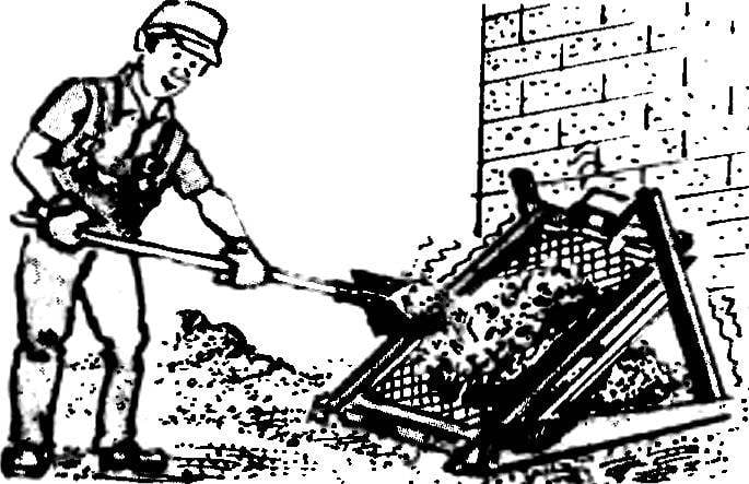
In the construction of cottages, garages in the farm economy often have to sift through loose building materials, soil or garden soil. It uses a special device — the so-called roar. His classic version of the frame with the grille installed on the box is a very cumbersome and inefficient. I tried to make it mechanized, as well as more compact and quiet compared to industrial samples.

The first electrographic happened to me not entirely successful. However, the second, revised, was to meet all planned requirements. For the manufacture did not have any need of scarce materials and high qualification of the contractor.
The design consists of bases, uprights, frame, motor, props and ties. Indicated on the drawings dimensions are indicative and may vary according to local needs and capabilities.
 
The base consists of two hollow bars, each made of two boards connected via spacers. The rods of the Foundation drilled holes Ø 14 mm.
 
Two sloping rack — bars of a cross section of 60 × 80 mm. At one end of each bar is a hole Ø 14 mm, while the other slot. Stands inserted between the plates of the base and are fastened with studs and nuts M12.
 
Frame is created of bars whose lengths are chosen depending on the dimensions of the existing grid, and the ratio of the estimated load. With brackets, the frame is installed on the lower coupler. To the upper floor she is suspended on a spring.
 
Motor (vacuum cleaner “Buran”) is fixed to the upper edge of the frame and is completely enclosed. The presence of casing is required. It protects the motor from contact with the ground, and for security purposes, protects the rotating eccentric shaft. To sift the material is not scattered in all directions on the sides of the frame are nailed boards.
 
Fig. 1. Rumble device for sifting granular materials.
Fig. 1. Rumble device for sifting granular materials:
1 — bracket (2 PCs.), 2 — base (2 pieces), 3 — pin M12 (2 PCs), 4 — coupling (2 pieces), 5 — grid, 6 — hour (2 piece), 7 — frame, 8 — circuit breaker 9 — electric motor; 10 — protective cover 11 — spring (2 PCs.), 12 — backstay (2 PCs.).

To make the construction of the oscillatory motion I refused to gear with the ratchet due to the complexity of manufacture and it produces a strong noise. Vibration is produced by unbalance of the motor shaft. The Cam is made from an ordinary wooden chocks. Selection of its shape and weight achieves the desired frequency and amplitude.
 
Back up (to give rigidity) are made of wire diameter 6…8 mm; ties and stud — rod threaded M12 at the ends.
 
Doing a further upgrade, I installed it on a rumbling device which automatically turns on or off the engine depending on the load on the frame. This allows to exclude idle cycle operation, save electricity and increase the life of the structure as a whole.
 
Work automation in the following way. When you load frame is lowered down and presses the S1 button. Its contacts close the circuit of the motor. It starts to rotate and shake the frame. At the first “failure” of the frame from the vibration she presses the button S2. That, in turn, closes the supply circuit of the electromagnetic relay, which the contacts K1 cambiocorsa, and the contact K2 disconnects the field winding (start) of the engine. Thanks to the first locking relay starting winding remains disconnected for the duration of the work. After sifting the material, the load frame is removed. She pulled the springs up and opens switch S1. The scheme returns to its original state.
 
Button and relay are installed on the three boards. Thus between cards of buttons S1 and S2 are two springs that serve to reduce the stiffness of the shocks and the steady closing of the contacts when the frame is loaded, and between boards buttons S2 and relay — four springs needed for a later closing of the contacts S2 and to preserve them from mechanical damage due to vibration. In the device are standard buttons from electrozone, relay type mku-48 (or any other with a working voltage of 220 V). Taken from the spring garden shears. The body is made from trimmed bottles of shampoo. The selection of their diameter to achieve the necessary water-resistance. Fasteners circuit breaker is done (with clamps) to one of the stands. This method allows you to adjust the time of the closure of the S1 switch in accordance with the load.
 
Fig. 2. Automatic control device.
Fig. 2. Automatic control device:
1 — cover, 2 — button S1, 3 — Board (PCB, 3 items), 4 — spring (6 PCs), 5 — button S2, 6 — relay mku-48, 7 — housing, 8 — pin M4 (3 PCs.), 9 — bushing (3 PCs.).

Kept crashing disassembled indoors, protected from moisture and snow.
 
Those who want to produce such a device, the experience two years of operation, their roar I want to give some recommendations. First, the transition of the power wires from circuit breaker mounted on a rack to the motor and mounted on the frame, it is advisable to carry out through the bottom edge of the frame. Second, should not be too short frame. The attachment point of the spring is desirable to choose as far as possible from the engine, which allows to increase the amplitude of oscillations. One last tip: to avoid electric shock during operation, it is necessary to ground the engine block or use a separating transformer.
 
P. SHERSTOBITOV, Perm

Recommend to read

  • ULTRALIGHT “DRAGONFLY”ULTRALIGHT “DRAGONFLY”
    Dear fans of aviation! This article may be useful for the development and construction of a light helicopter. Offer - to rotary-wing aircraft (AV-1) is the fruit of a long fascination...
  • C-6: SIMPLICITY AND RATIONALITYC-6: SIMPLICITY AND RATIONALITY
    Winter operation of all-terrain vehicles in the northern regions of our country places a number of specific requirements on it. So, to reduce resistance to movement, the machine must have...