
 That’s already more than a dozen years G. Malakhov works as the chief mechanic tool shop of one of Moscow’s aircraft factories. But even more time (13 years) he is engaged in Amateur technical creativity, without which it is not at all his present and future. On account of his snowmobiles, motorcycles and other self-propelled equipment. Currently, life is made of Gennady Yurievich to move away from its “profile” — he made several high-precision woodworking machines for various purposes, set them next to the parental house in a village near Moscow and provides its villagers and residents of the nearby holiday village beautiful lumber that helps to survive him and his large family. But about the main thing he forgot — next year plans to collect long-planned amphibious with aerodiesel. Today we will focus on a small tractor, made by him mainly from the fact that was accumulated over many years in the garage.
Since my teenage years I could not safely pass the motor in need of a good renovation. All free time spent in the garage or workshop, where I worked my countrymen, a collective farm mechanic of the old school. More than a dozen engines were restored under his leadership.
Later came the idea of self-built self-propelled equipment. So there were my bikes, tricycles, snowmobiles and all-terrain vehicles on low pressure tires. Not all of them have represented the height of technical perfection, but most fit for purpose, and a younger brother and his friends got a lot of pleasure riding on them. I am also after something that was embodied in metal and brought to mind, began to pursue the thought of a new or improved machine.
In adulthood has been forced to produce more of the required units, including mini-tractors for all kinds of jobs on the plot. By that time I already had a little experience in this area were built wheeled tractor on the basis of knots and units of tractors T-25 and T-40, but it was too big and heavy.
For “gardener” was chosen the most simple constructive scheme — lightweight welded frame from steel profiles, which fixed all the major components and assemblies of the machine. The frame consists of two side members, the front cross member, rear cross member middle bracket rear axle beam with eye hinge suspension of the front axle, a platform for installation of the unit, switch gear and pump, the base of the seat.
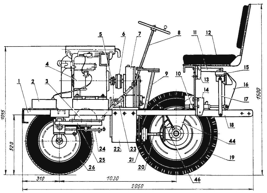
General view of the tractor (side view of the left wheel is not shown):
1 —frame; 2— fuel tank; 3 —steering gear (worm gear from the cutting machine); 4 — engine UD-8: 5 — a pulley of the hydraulic pump; 6 — elastic coupling (from the car “Lada”); 7— universal unit; 8 — steering shaft and transmission (ZIL-130); 9 — front wheel (St3, pipe 42,3×2,8, L380); 10— hydraulic cylinder (ZIL-130); 11 —upper rocking (St3, strip 30×15, Ь220); 12 — seat; 13 — upper bracket (agricultural equipment); 14 — bottom brackets (from agricultural equipment); 15 — strip (St3, stripe 60×25, L520); 16 —the lever (St3, the sheet s12); 17 — thrust(St3, strip 20×12, L340, 2); 18 —tow strap (CT3, strip 60×15, L500); 19 —rear wheel (UAZ-469); 20 — the propeller shaft; 21 — elastic coupling (from the car “Ural”); 22—box CAT (D16T sheet s12); 23 —pump (ZIL-130); 24 — a Pitman arm (St3, the sheet s10); 25 — beam left steering gear mounting (St3. the channel 65×36, L410): 26 front wheel (from the car “Lada”); 27— the drive sprocket of the gear (z = 20); 28 —belt drive pump: 29— beam suspension front axle; 30— swivel pin; 31 — gear box (milling machine); 32 is the driven sprocket gear (z = 13); 33—beam front axle (St3, pipe 60×4, L600): 34 — the transmission chain; 35 — reducer of the rear bridge (corner helicopter gearbox): 36 — lever for left wheel; a 37 — adjustable tie rod 38 to the housing of the bearing unit; 39 — longitudinal steering rod; 40 — tie rod; 41—mount switch gear (D16T sheet s10): 42 switch gear (cutting machine): 43 — engine mount (rubber, 4 pieces); 44,45,46 — mounting brackets rear axle (St3, sheet s20)
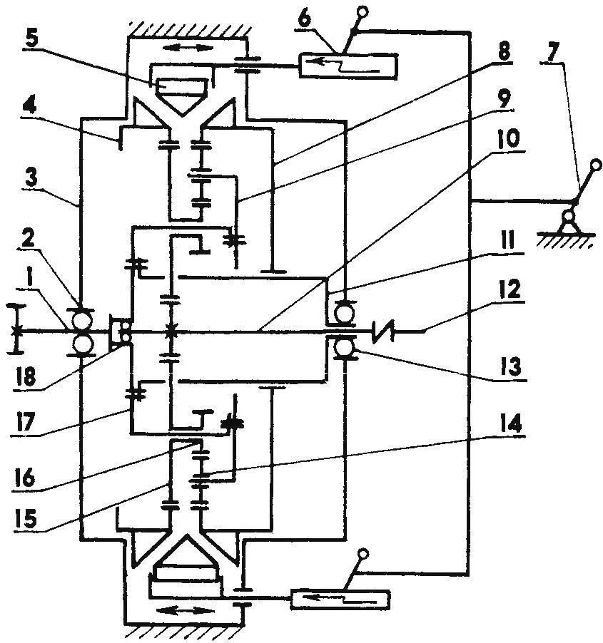
The kinematic diagram of the universal unit:
1 — output shaft; 2 — bearing 160209; 3 — body; 4 — the left sun wheel (z = 57); 5—compression ring; 6 — a rack and pinion mechanism; 7— the control lever “reverse — idle”; 8 — right sun gear (z = 54); 9 — output carrier; 10 — input shaft with the ring gear (z = 15); 11 —intermediate bushing; 12— shaft; 13—the bearing 160208; 14 — the idler wheel (z =15,3 PCs.); 15 —larger pinion (z = 21); 16— smaller pinion (z = 12); 17 — carrier; 18 — bearing 203
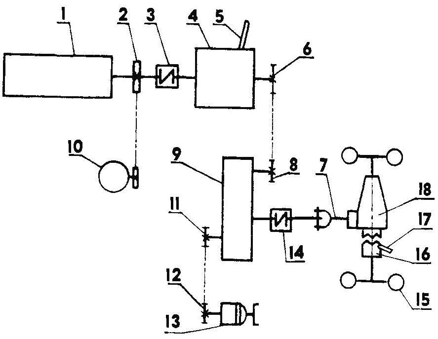
Scheme of transmission:
1 — engine; 2 — a pulley of the pump; 3,14 — flexible coupling; 4 — a universal unit; 5 — control lever “reverse — idle”; 6 — sprocket (z = 16); 7 — propeller shaft; 8 — sprocket driven (z = 13); 9 — gear box; 10 — pump; 11 — sprocket driven gear (z = 13); 12 — sprocket gear (z = 20); 13 switch gear; 15 — wheel rear axle; 16 — Cam clutch; 17— the lever of inclusion of the left wheel; 18 — a reducer of the rear bridge
Oscillating front axle equipped with a steering mechanism mounted on two steel channel, welded to the beam bridge. To the mechanism from the handlebar summed up the driveshaft. Turn of the front wheels is through a system of rods and rockers.
Rear axle, however, as the front has no springs or shock absorbers and rigidly attached to the frame of the two side and middle brackets.
As the power plant used 8-horsepower four-stroke 4-cylinder engine with forced air cooling UD-8 from mobile plant. It has a number of advantages over other engines, with good fuel economy, exceptional quietness and ease of starting in all weather conditions.
The motor is mounted on four rubber shock absorbers. The PTO output shaft UD-8 is a belt drive to a hydraulic pump, intended to drive the tow mechanism, and through the transmission to the rear wheel axle. Some loss in weight of the transmission due to the use of boxes and switch gear from the decommissioned milling machine is overcompensated by universal light unit and a reducer of the rear bridge, which is used as modified (if necessary, you can connect the Cam coupler enable left wheel) angular gear box tail rotor of the helicopter.
About universal unit it is necessary to tell separately. It is a planetary reduction gearing having two sun wheels movable in the axial direction of the clamping ring between them. When you move the ring via the rack and pinion is braking the left or right of the sun gear. In the first case, reduction ratio I n = 4,8 without changing the direction of rotation of the output shaft of the gearbox. When braking, the right sun gear is switched to reverse (reverse tractor) and increases the gear ratio to 7.3. If the ring is in an intermediate position, the engine is idling. The control lever “reverse — idle” have a simple three position lock located on the housing of the unit. Thus the Assembly performs three functions: gearbox, clutch and switch the direction of movement of the machine; and in combination with the transmission (transaxle) ensures the tractor ten speeds forward and ten back, which is very convenient when working in different soils.
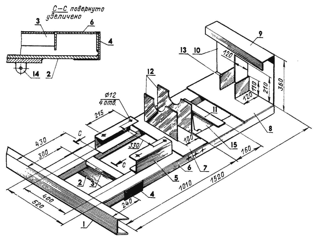
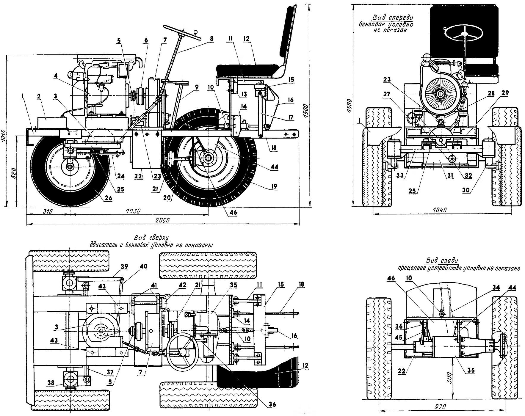
Frame (all parts are made of St3):
1 — bumper (channel 120×52): 2 — beam suspension in the front axle (strip 105×10, L520); 3 — front cross member (channel 65×36, L280); 4 — bracket (area 70x70x5.1Л25); 5 — stand under the engine (channel 100×46, L315, 2); 6 — spar (channel 120×52, L1515); 7 — platform (sheet 520×210, s15); 8 — seat base (sheet 520×200, s15); 9 — beam seat mounts (channel 100×46, L520): 10 — front seat (sheet 520×308, s15); 11 — rear crossmember (sheet 400×130, s20): 12 — universal stand Assembly (sheet 300×200, s15): 13 — solitaire (leaf s20, 2): 14 — eye suspension joint suspension front axle; 15— middle bracket rear axle
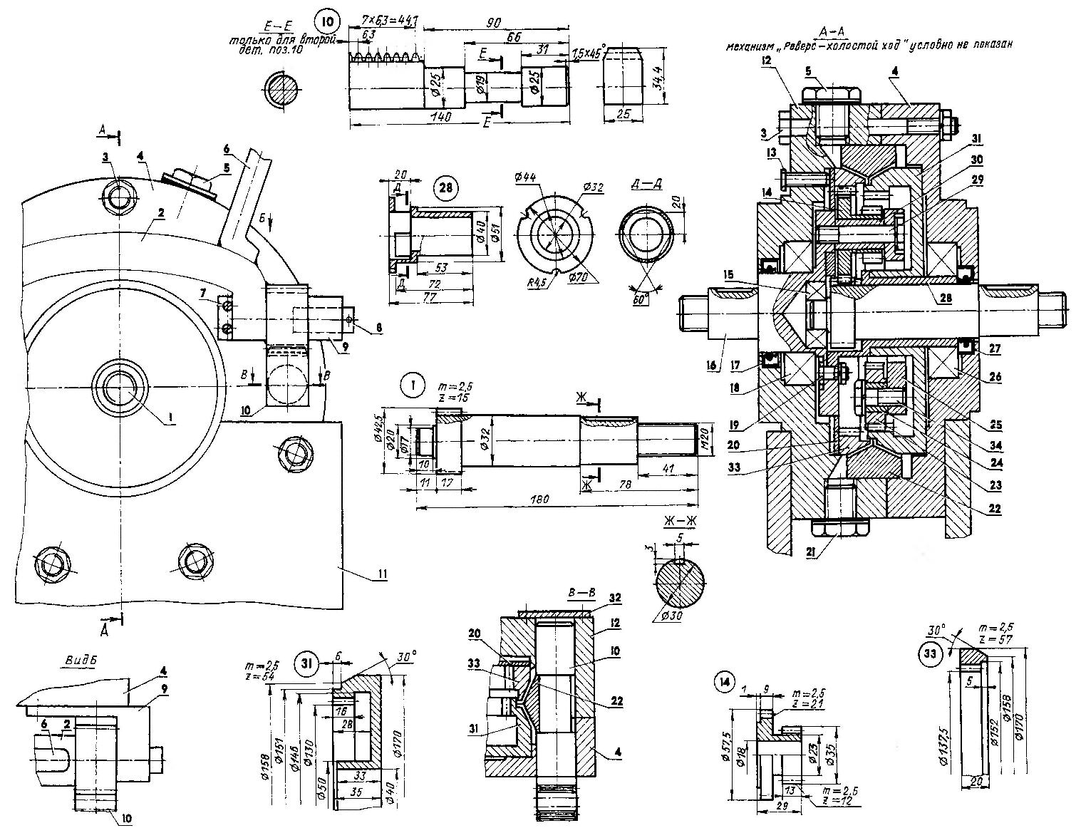
Universal unit:
1 — drive shaft (30KHGSA); 2 — rocker arm (ft3): 3 — M10 pinch bolt (7 PCs); 4 — the right of the ladle body (D16T); 5 — filler cap (bolt M20); 6 — lever “reverse—idle” (St3, rod Ø15); 7 — M6 screw; 8 — axis growl and management (St3, rod Ø15, 2); 9 — bracket (St3, 2 PCs.); 10 — rake (30KHGSA, 2); 11 — rack; 12 — the left half of the body (D16T); 13 — adjusting screw M8 (5 PCs); 14 — Satellit (30KHGSA, 3 pieces); 15 —the bearing 203; 16,25 — carrier (30KHGSA); 17,27 — cuff 18 — 160209 bearing; 19 —a bolt M8 (3 PCs); 20 ring (bronze); 21 — drain plug (bolt M20); 22 — clamping ring (bronze) 23 — the idler wheel (z = 15, 3). 24,30 — bushings (bronze) 26 — bearing 160208; 28 — intermediate bushing (bronze); 29 —pinion (M10, 3 pieces): 31 —right sun gear (30KHGSA, z = 54); 32 — technological plug (2 PCs): 33 — left sun gear (30KHGSA, z = 57); 34 — a bolt M10 (3 pieces)
Constructively the unit is enclosed in a sealed housing. Carrier and output shaft rotate in the ball bearings, and the pinion gear and idler wheels — bronze bearings, with grooves on the friction surfaces for the passage of oil. (By the way, the body is filled with 200 — 300 g automotive gear oil.) Carrier consists of two parts connected by axis satellites. The output shaft is simultaneously the pillar of the right sun gear, but the speed and direction of rotation are different. So between them there is an intermediate bronze bushing, rigidly fixed to the carrier, and the engagement of the ring gear shaft with large rims of satellites going through the slits in her. The gap between the sun wheel and the clamping ring can be adjusted by moving along the axis of the left wheel, using the five screws.
The presser ring is made of two diametrically spaced groove. The position of the ring relative to sun wheels is determined by the position of the rails (or rack pull), installed in a special socket of the housing unit and at the same time in the ring grooves journals of their cylindrical parts, equal in length to the thickness of the clamping ring, and the diameter is the width of the groove. During Assembly of the unit only one pull pre-assembled with the right portion of the housing, a sun wheel and clamping ring. To install the second thrust portion at its cylindrical belt with a diameter of 25 mm is cut to 19 mm and is inserted into the housing, followed by 180° after its final Assembly.
In General this unit is designed for use in amphibious aircraft propulsion, but for now we can assume that it is being tested in the “severe” garden conditions.
G. MALAKHOV
Recommend to read
 GLUING — SO RELIABLE!
Use Scotch transparent tape — in many cases much more convenient than glue. Only one disadvantage: it is difficult to glue the long leaves: sticky tape curled, deformed, and the quality...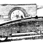 CORD, SPEED 2,5
Control line racing model class 2.5 cm3 designed and manufactured in a self-similar laboratory of the Palace of pioneers and schoolchildren of the Pervomaisky district of Moscow under...
