To ensure the IED power supply is the AC adapter. It can also be manufactured in any home workshop, the benefit of a circuit diagram of the adapter of the particular complexity does not differ (Fig. 2). It uses a step-down transformer with a voltage in the secondary winding 9 (“vyhodnoj” mnogoplanovo from any old radio), integrated stabilizer КР142ЕН5А, circuit breaker Yes, three capacitors, two of which — bolsaescola, electrolytic.
Fig. 2. A circuit diagram of a network adapter for hours.
Of course, can be adapted to any other power source capable of providing at the output 5 to 15 VDC. Note, however, that at increased supply voltage increases the self-induction EMF induced in the coil of the stepper motor. So, in order to avoid any complications will have to connect parallel to the load Dohnanyi semiconductor Zener КС162А limiting emissions.
The device used in integrated circuits series 564 (DD1, DD3), which can be replaced К561-m (however, this will increase the dimensions of the PCB), though as DD2 is only recommended series К561, and DA1 — КР142. КТ3102 transistors (VT1, VT4), КТ3107 (VT2, VT3) with any alphabetic index at the end of the name can be, if necessary, to replace, respectively, KT315 and KT361, and the bridge rectifier КЦ405А (VD1) is at a similar or even more powerful diode Assembly.
Capacitors, it is desirable to choose of the most common KM-5 (C1), KM-6 (C3 in Fig. 1 and C2 in Fig. 2), K50-35 (C1, C3 in Fig. 2) and resistors — from as available S2-22-0125 or their analogues.
A more stringent approach to the selection of the quartz resonator which must be tuned to the frequency of 32,768 Hz. Such used, in particular, push the manipulators of “mouse”.
The clock accuracy is determined by the precision setting of the frequency of the oscillator. Alignment here is set up by the capacitor C2. This procedure should be performed if possible, using elektronischen frequency.
The installation is carried out on a printed circuit Board from a two-sided glass epoxy or phenolic paper sizes 60x40x1,5 mm (Fig. 3).
Fig. 3. A printed circuit Board, a homemade device.
V. VASILENKO, Sverdlovsk, Luhansk region, Ukraine
Recommend to read IN BATTLE WINS DESIGNER… The lightest balsa frame, powerful nitro engine made with your own skilled hands and is able to "pull" almost weightless Model in almost all its evolutions... Are models of air combat's... “ROMNET” Resident of the city of Romny, Sumy region A. Zinenko reports motonartah "Romney". "Motor scooter "Tula 200" allows to reach the speed of 25 km/h. Motonarty very happy, — says A.... 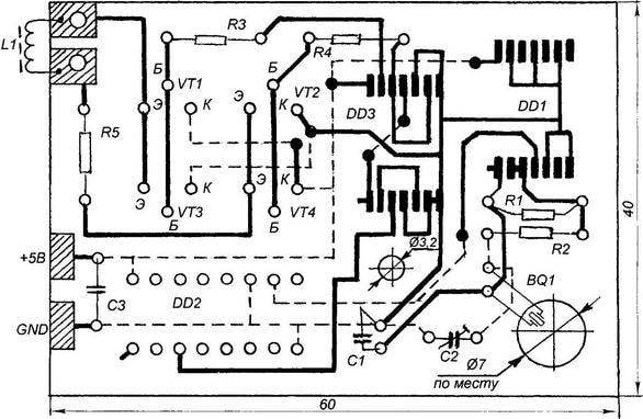
 Currently available a variety of models of wall elektromekhanicheski quartz watches with stepper motor. They are, as a rule, uses unpackaged integrated circuit — the oscillator/divider with an external quartz resonator coated with black compound. And had to happen that this e-node has failed in the clock, served me faithfully for years.