
 Good motor sudomodel, as they say, will not spoil. Just where in the Russian province it? Because most of the available domestic microelectrophoresis focused on the use in children’s toys, unfit for use (without major modifications) in RC models. The structural simplicity of these engines is often at odds with the requirements of duration, resource and, most importantly, threatens the high level of noise that reduce the reliability of the instrument radio. Imported good-quality motors (alas!) prohibitively expensive.
In search of suitable motors resourceful modelers are trying to adapt what I find sometimes in precision instruments manufactured in the old days, by order of the military. In particular, hunt for microelectromechanical series DP, DPR, DPM, having high reliability and a fairly large resource. Out and hitting the market at an affordable price conversion counterparts of these engines. Only they are designed mainly for use in DC circuits with the voltage V. 27-28 Although almost all previous DP, DPR, DPM, and their new successors is quite efficient at lower supply voltage, but… What the Modeler does not want to squeeze out of the engine on your model the maximum possible!
For large models, this problem is easily solvable by placing the appropriate number of galvanic batteries. But for small, where there is little free space in the case to cram a good 28-volt motor can hardly be justified: when forced limited power supply that can give the load only 25-30 percent of its nominal power.
A universal solution may be the equipment of the model electronic Converter, capable of boosting the source voltage from the two low-voltage batteries to the value specified in the passport of the engine. As shown by simple calculations, this power supply is economically justified even despite the additional loss of energy that inevitably appear when using the device.
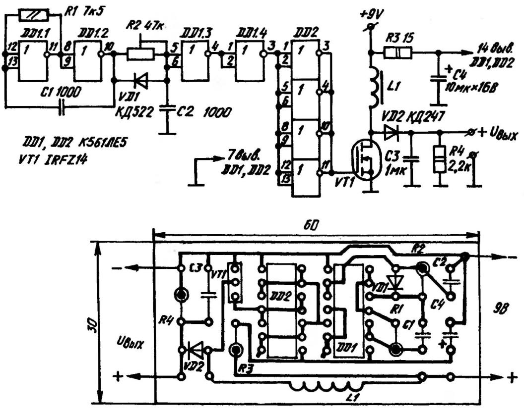
A circuit diagram and a printed circuit Board, voltage Converter 9/27—28 In
Indeed, in the same options apply to the motor nameplate 27-28, need series connection of six batteries at 4.5 V, the acquisition cost of which will amount to a considerable amount. Work the same “premortem” — class ship models EK, EN, EX have at a standard distance (15m for models with hull lengths of less than 600 mm and 50 m — for models with hull lengths from 600 to 1250 mm) 15-30 (the Rules provide four rounds of the competition), and in radioklass — two rounds for 4-5 minutes.
During this time, a bulky set of power supplies will not have time until the end of your spend unnecessarily large amount of energy.
That is installing electronic voltage Converter for any of the named boat (equipped with motors of the DP, DPR, DPM and the like, requiring 27-28) is not a extravagance but a necessity. And easy recommended devices works inspiring.
Take, for example, a master oscillator. It’s a simple and reliable technical solution on the chip DD1 type К561ЛЕ5. The frequency of the generated pulses is set by capacitor C1 in conjunction with a constant resistor R1. The duty cycle exhibited “regulirovania” R2. The optimal ratio of signal duration to the length of the pause is determined as 2:1. Control — at the gate of the transistor VT1.
All four logical element of the second К561ЛЕ5 marked on the circuit diagram as DD2 connected in parallel and used as an amplifier to control the powerful field transistor VT1 brand IRFZ14. The exact analogue of this “fieldwork” foreign production, took a strong position on our market of electronic components seems to be no. However, in the case of urgent need you can still replace it with domestic КП921А (according to some critical parameters of both transistors approximately correspond to each other).
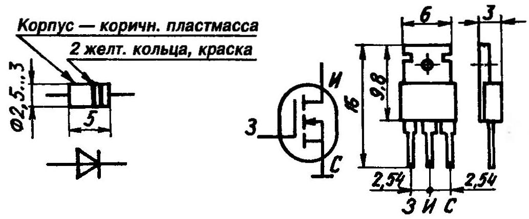
The dimensions of the symbol of the conclusions КД247 diode and power MOSFET IRFZ14 recommended for use in the design of the inverter
Inductor L1 is, perhaps, one of the circuit elements, which depend on the energy loss during the voltage conversion. In the original it is a 200 turns, wound wire ПЭВ2-0,2 two ends glued to each other ferrite core (diameter 5 mm, length 20 mm) from the module information rays old tube TV. However, it is also acceptable ferrite cores, P – and W-shaped ferromanganese or fragments of rings 2000NM (2500-3000НМС). It is possible and the use of the throttle without any core, however, the consequences of losses in this design are difficult to predict.
The diode VD2 also an important element of the scheme. Most suitably the parameters КД247. Resistor R4 provides a continuous current mode in the inductor at no load. Specified in the scheme the face value is defined given the fact that the electric motor to the inverter can be connected not directly but via a control circuit (otherwise the voltage threatens to come close to a dangerous line 70).
Voltage Converter, accurately assembled from a known good electronic components on the Board size 60x30x1,5 mm of one-sided foil fiberglass, and connected to 9-volt power source, usually immediately starts to work. Debugging time is reduced to clarification of the value of the resistor R2. Optimum find with the switched-off transistor VT1, focusing on the fact that the duty cycle was 2:1.
For maximum reduction of interference from the running of the inverter, it is advisable to place it in a fully shielded (metal) box. And with a maximum distance her from omegasoftware of components and systems advanced.
In conclusion, it is useful to emphasize that the prototype voltage Converter 9/27—28 successfully tested for model ships, equipped with both one and two types of electric motors DPR-62, DP-30, DPR-42, DP-20. It works extremely well, with an efficiency of about 80— 85 percent.
Vitaly SAVELYEV, head of ship modeling circle in the CCC Raduzhny, Vladimir region
Recommend to read
 YACHT FOAM
For training younger students in ship modeling circle city of Kaspiysk, Dagestan Soviet Rupublic under the leadership of V. Tolchennikov developed a model of the yacht foam. It is easy... Mi-2
Mi-2
To develop a single-rotor Mi-2 helicopter with two turboshaft engines, designed to replace Mi-1, launched in 1960, its First flight took place in September 1961 Serial production began...
