Now more about the model itself, which we call “Firefly-2”.
For the wing, we chose a PLANO-convex profile, which allowed to reduce the size and use for the manufacture of the most affordable materials. The mass of the model with the engine does not exceed 400 g, which allows quite stable to fly even at the nominal engine mode.
Fig. 1. The training model of air combat “Firefly-2”.
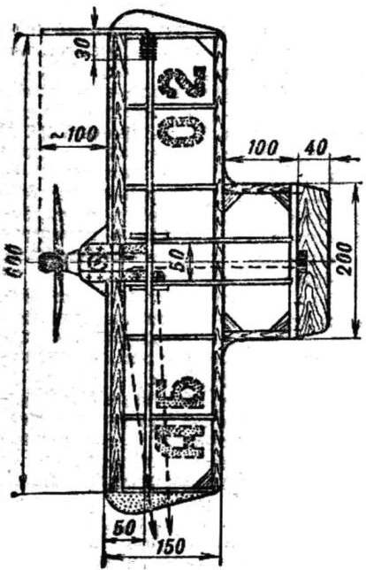
Fig. 2. The layout of the model.
A few simple devices п0зволило to dramatically reduce the number of breakdowns and accidents during landing, improve the survivability of “Firefly.” In particular, the traditional ballast load external wing took the form of a protective clamps from securely soldered together and attached to the end of the wing with thread and glue segments of steel wire Ø 2 mm scan Length great staples — 420 mm small — 220 mm.
Nut propeller with reverse taper; this is necessary to fix on her vinyl chloride tube with a length of 20 mm. the tube is inserted a rubber tube that protects the engine and mount from damage. For the nuts only have to make steel strip of a thickness of 3 mm special wrench-screwdriver. The propellers we use, as a rule, standard, stamped from elastic plastic.
Almost all the details of the model, in particular ribs, motor mount, sub bars, liners, scarves, sawed jigsaw of thick birch plywood with the thickness 3-3,5 mm. Below details are better perceived external load, the direction of the fibres of the outer layers of the plywood plates should correspond to the depicted in figure 4.
Besides the plywood, you will also need the pine slats of the following sections: for the rear edges of the wings 3,5X10 mm, for spars 4X4 mm, for front-edge — 6X6 mm.
“Louki”, glued along the front edge of the wing, cut from plywood strips with a width of 15 mm or veneer (thickness 1-1,5 mm).
All wooden parts after treatment and mutual adjustment are impregnated with a liquid nitrocream — it increases their strength, moisture, moreover, this primer increases the reliability of bonding.
The frame of the model it is most convenient to collect on a level plane, the connection of the parts — nitrocream. After complete drying all edges and seams are frenched and the external wing mounted safety brackets. Docking of these gellately wing will be far more reliable if the prior ends of the brackets are wound in a single layer of thread. Using the same thread bracket attached to the end rib of the wing.
Take-off model type “the Firefly” — with it. After starting the engine the mechanic is taken for the end of the outer wing, inspects the site and at the command of the pilot catapulted model, trying to make it to the line tangent to the circumference of the flight.
Before starting the pilot needs to take the control arm red condom up and inspect the pad. Then, giving the mechanics team on the release of the model in flight, to make the first move with your hand during flight. Not recommended for first time running “to work” elbow PLI brush — enough to raise and lower the whole arm’s length. This allows us to reject the Elevator on the model is very smooth, and therefore an aspiring athlete faster mastering the techniques of management. It is best to train on the ground with soft grass, thus preventing the model from significant damage.
On the inner end of the wing is bracket wiring cord — it bends steel wire Ø1 mm. the wing Tips are cut from foam and glued to the end ribs.
The wing is covered macalintal colored paper (with the help of nitraria) or thin Mylar film (with glue BF-2). Model marking consists of the initials of the Modeler and a two-digit number — the sequence number of the model.
Hog and rocking the control of aluminum sheet with a thickness of 1,5—2 mm. Holes for carabiners and a pull — Ø2 mm on the axis of rotation (screw) — ø 3 mm. Carbines are bent of steel wire Ø1 mm, control rod wire Ø2 mm.
The Elevator is cut from a plywood plate with a thickness of 1-2 mm. Beneath the hog steering it is necessary to cut a narrow slit for the passage of thread with a needle. Setting the pig in place, “sew” it to the surface and promazhte glue and reinforce with a strip of nylon fabric. The Elevator hinge is fixed on the model thread No. 10. Previously along the axis of rotation of the steering wheel will natuerliche hole Ø1 mm.
Fig. 3. Fuel tank.
Fig. 4. The main parts of the model “glow-worm-2” (material — birch plywood):
1 — strengthening spar, 2 — the Central rib, 3 — rib wing, 4 — part motor, 5 — kosinka, 6 — base motors
The fuel tank soldered tinplate, drainage and water pipes — copper tube external ø 3 mm. Tank engine is mated to a PVC tube with an inner bore of Ø1. 5-2 mm. tank Design depends on the type of used engine. If the model assumes the installation of the engine front distributor (via the crankshaft), the tank is better to do long and low. When you use the same engine with a nozzle on the back wall of the tank will have to do more short and high — this will provide access to the inlet of the carb. Tank volume is about 20 cm3. This is enough for training runs and club events.
Control arm model wooden. After it will be drilled four holes, sand the surface on the skin and cover with a nitrovarnish. The upper end of the control arm plate red enamel. Through the holes is passed a nylon cord, as shown in figure 2, the ends of it are fixed carabiners wire OVS Ø 1 — 1.5 mm. the Handle of this type can very precisely set the Neutral position of the Elevator. Securing the cords between the carabiners on the handles and carabiners on the model, check the strength of the entire control system. To do this the easiest way a household spring balance. The control system must withstand a load of not less than 8 kgf.
If you are preparing to launch several models, carefully make sure that the distance from the centerline to the axis of the control arms were all the same (±40 mm).
Before you start be sure to mark the site — you can do it with bright paint or flags. The latter will need at least 16 pieces. When marking is necessary to designate the centre pad — round Ø 5-6 m and the range of flight models.
A. MARCHENKO
Recommend to read HOW TO SHORTEN THE BOLT To shorten a long bolt or stud, such a task is not so rare encounter tinkerers. In order not to damage the grip of the thread, I suggest to use a simple tool, which is a metal strip 5-10... TABLE… CHAIR A long-standing desire to have a coffee table brought me to a furniture store where there was at least a strong desire to make this table their own — these were there prices. Turned up... 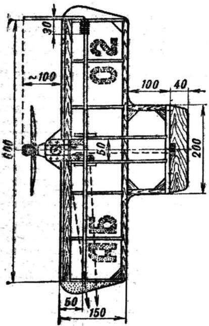
 Readers already familiar with the workings of the Chisinau children’s club “Firefly” of the Ministry of Moldova. Last year, the “M-K” printed drawings, model air combat “Firefly”. This simple, durable and unpretentious bouzouki like many beginning modelers, as we judged by the numerous sent to our club e-mails.