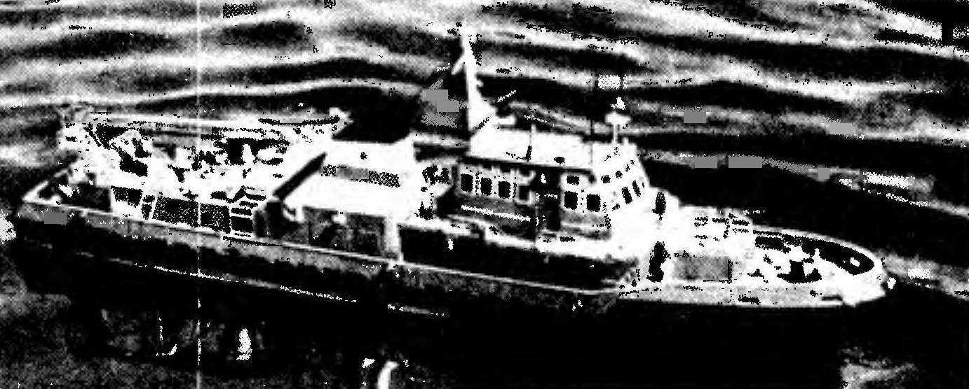
 Model boats ROSTOK. There is a class of courts, representatives of which can be found in all sea countries, to see in any major seaport. This court, lifeguards, created to provide assistance at sea of vessels in distress and the ships, fighting fires, repairing hull damage, pumping water from flooded compartments, lifting off the rocks and towed into port. Such vessels vary with displacement, speed and technical capabilities. A significant group of such vessels constitute a fire and rescue boat. We are introducing our readers-modelers one of these boats, called ROSTOK — such vessels operate in the seaport of Rostock (Germany).
Fire-rescue boat GREENORE is designed to assist the crews of ships and aircraft in distress in coastal waters of the seas and on inland waterways. The boat is a twin screw ship with the superstructure and the pilot room, equipped with a lifting device in the aft. The length of the boat 36,2 m width of 7.57 m. the power plant of the boat consists of two diesel engines with a capacity of 900 horsepower, rotating propellers with a diameter of 1.65 m.; boat speed — about 14 knots. For fire fighting the vessel is equipped on the superstructure and the lifting device fixed fire barrels to supply water and foam.
We offer modelers model boat GREENORE in 1:33 scale with which to compete in the class YONG on 25-meter distance.
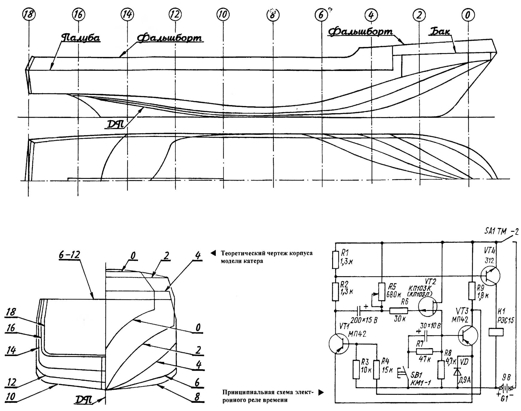
The hull would be best to utformat on the disc of epoxy resin and fiberglass. To make such a CD, you need to start to make a kind of “skeleton” of the case in strict accordance with his theoretical drawing cut from thin plywood or cardboard frames and put them on the long straight bar-“the ridge”. It is necessary to consider that on a theoretical drawing shows a section of the housing at its outer contours, therefore, in the manufacture of frames for the “skeleton” of the disc their path should be lowered by the thickness of the fiberglass shell. Next, the foam is cut into billets, which are pasted between the frames.
Before assembling makes sense to pre-process the foam blocks to remove the “extra” material in accordance with the contours of the neighboring frames.
The processing of the foam should be razor-sharp tools, long flexible knives, plows, knives joints and tiny planes. To control the shape of the case you can use flexible strips of plywood, polystyrene or PCB — applying the strip to the adjacent frames, it is easy to identify zones of “neparasti” curved surfaces.
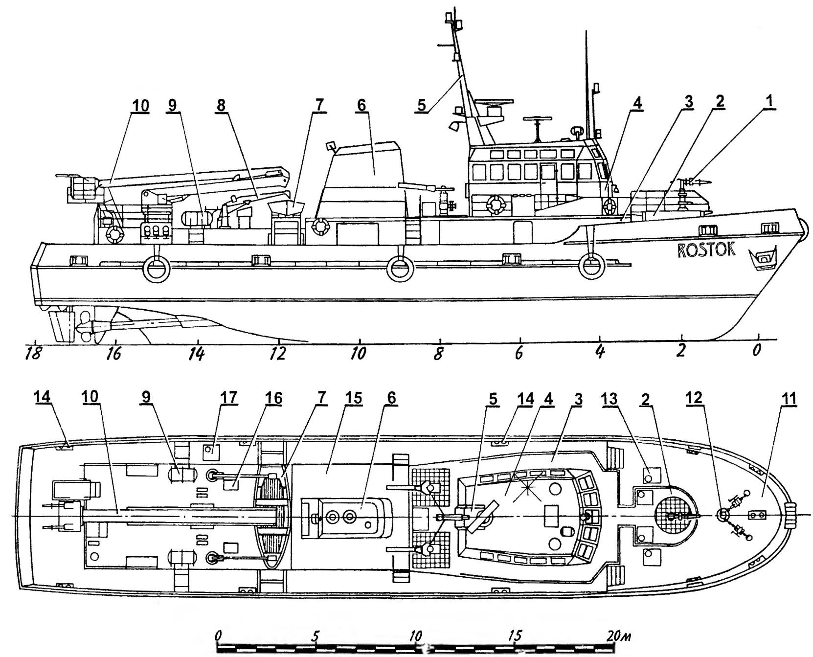
The layout of the fire and rescue boat ROSTOK:
1 — tank fire barrel: 2 — deck tank fire trunk; 3— the superstructure of the wheelhouse; 4 — the wheelhouse; 5 — mast with radar antenna; 6 — flue pipe; 7 — lifeboat; 8 — sloop-beam: 9 — liferafts; 10 — lifting device with working platform. equipped with two fire trunks; 11 tank; 12 — anchor-mooring device: 13,17 hatches: 14— bollards; 15 — cap machinery space; 16 — vent head
Finally bring the disc with sandpaper glued to plywood strips and wedges with surfaces of suitable curvature. If necessary, the disc cemented, to make it easier just ordinary plasticine.
The finished disc is covered with wax mastic (antiadhesive cover) and carefully so as not to rumple the soft foam, raspolirovyvayut. Good antiadhesive coating produced from the finest food wrap, which in the stores bagging groceries. It is sufficient to attach the film to the surface of the blanks and smooth hands, she immediately as if to stick, forming a smooth surface, not adhering to the epoxy binder.
To mold the housing best outdoors or in a well ventilated area. Depending on the thickness of the fiberglass to vyklicky shell will take from four to six layers of this material.
After curing of the binder housing barked and trimmed, the line of the bulwark; bulwark propisyvayutsya scuppers and openings for cleats.
Deck — of 5 mm plywood and cut holes for add-ons, and then pasted the coaming with a height of 25 mm. Fixed deck in the hull after mounting of engine and stern tube shafts and steering gear.
On the tank model placed a platform with a fire barrel, mooring and towing bollards, hatches, and anchor-mooring device, consisting of windlass, anchor chain, two lock pins and two anchors. For the descent from the tank to the deck of the ship there are two ladder that you want to recreate on the model.
Immediately behind the tank on the main deck is the superstructure, which is fitted to the wheelhouse with two rows of Windows around the perimeter. On the wheelhouse fixed mast with radar antenna, the antenna of a radio direction finder, the whip antennas of radio stations and spotlight. Behind the wheelhouse, on special pedestals are mounted two fire gun.
On the roof cap of the engine room is a chimney with bevels. Her across the body of the model on the lodgment is established Dinghy and two davits. Aft cap mounted lifting device. It consists of a rotary base, a compound of the boom and the working platform. The last are attached two fire gun.
The power plant is made on the basis of electric motor MU-30 (its working voltage 27 V, current consumption 5 A rotational speed of 7500 Rev/min, power 40 W, weight 0,6 kg). To drive screws used self-made gear reducer with a ratio of 1.33, which provides the rotation of the pair of output shafts in opposite directions with a frequency of 5625 rpm due To the fact that the possibility of manufacturing of gear wheels in most modelers is limited, start designing gear makes sense with the selection of ready pair of identical gears with an outside diameter of about 30 mm and a module of 1.5—2 mm. In accordance with their geometrical parameters are calculated dimensions of the housing of the reducer and its design, and then selected second gear pair gear ratio should also be about 1.33.
Details of the housing— sheet steel of 3 mm thickness, between them they are connected using four bolts with nuts and split lock washers. Shafts, steel, turning, gears and cog wheels are pressed onto them, which makes them quite reliable lock against rotation. Primary gear reducer is mounted on the motor shaft retaining screw with a conical tip. As the sliding bearings use bronze bushings, pressed into the base and the cover.
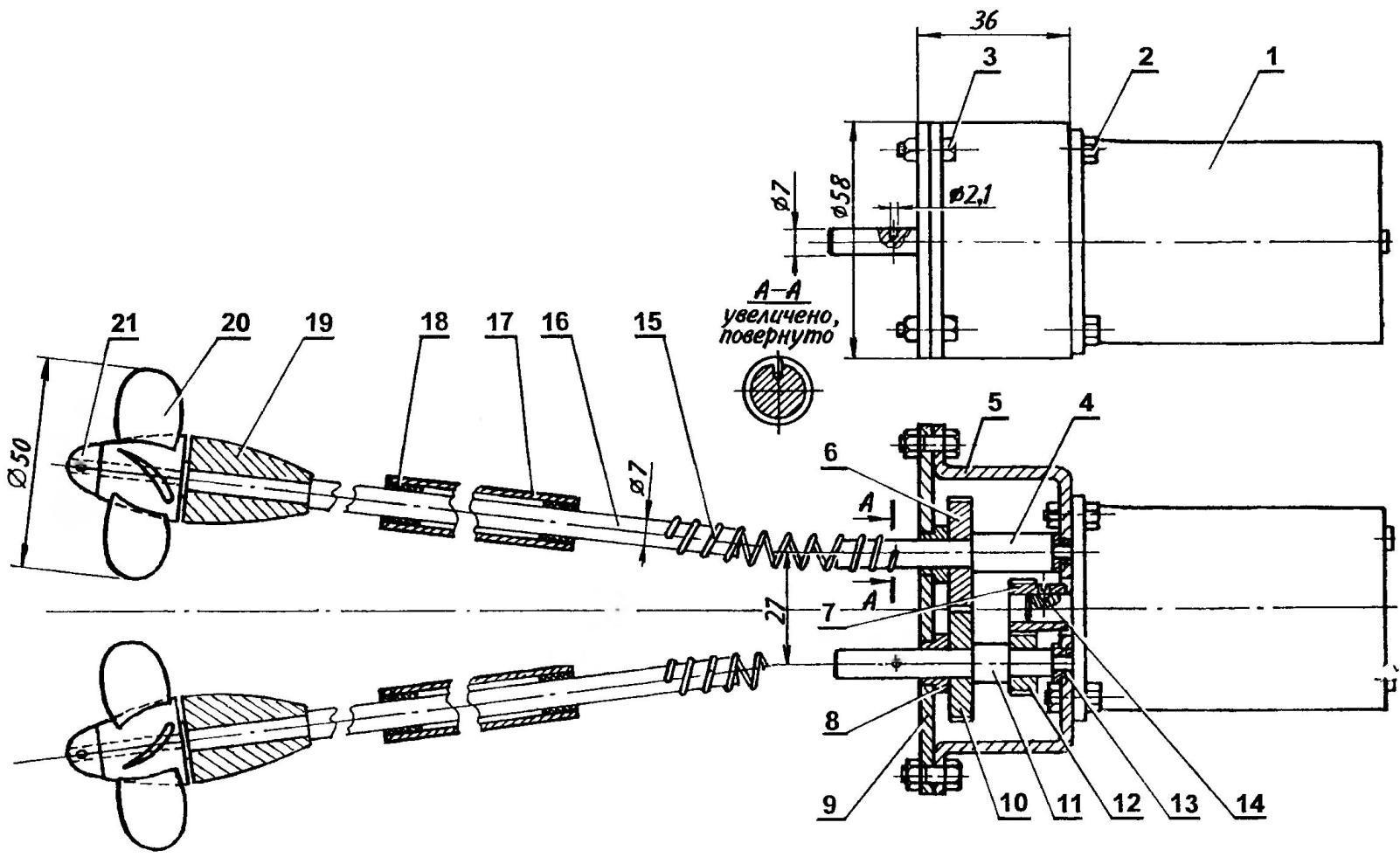
The power plant model boats (on the side view of the stern tube shafts are not shown):
1 — motor MU-30; 2 — a bolt of fastening of a reducer; 3 — a bolt of fastening of a cover of the gearbox; 4 — left output shaft of the gearbox; 5—gearbox; 6.10 — gear wheel; 7 — primary gear reducer; 8 — sleeve; 9 — housing cover, reducer; 11 — right output shaft of the gearbox; 12 — a gear wheel of the right shaft; 13— small bushing; 14 — locking screw primary gear; 15 — elastic spring coupling; 16—stern shaft; 17 — shaft pipe; 18 — textolite bushing; 19 — bracket stern tube shaft; 20— thruster; 21 — nut-fairing
The engine along with the gearbox is fixed on a frame cut from 10mm plywood and fixed to the housing at an angle of 4.5 degrees to the vertical.
Stern tube shaft diameter of 7 mm rotating shaft in steel pipes, in which from two sides glued textolite bushing; in the Assembly of the stern tube is filled with grease (for example, tsiatim). Prefabricated propellers, consisting of a brass hub and soldered thereto blades have a diameter of 50 and a pitch of 24 mm. Fastening each of the screws on the stern tube shaft—nut-fairing.
Each shaft and output shafts of the gearbox are connected by elastic coupling in the form of a spring with an inner diameter of 7 mm, a retinue of wire OVS 2 mm in diameter. To prevent slippage of the shafts to couplings, each of the shafts is drilled blind hole with a diameter of 2.1 mm, and the ends of the springs recurved hooks.
Powered motor from rechargeable batteries 2КНБ-2 total voltage of 25 V.
For performances in the competition the model must be equipped with a time relay. For this purpose it is better suited to improvised electronic relay, capable of switching used on the model engine MU-30 with an operating voltage of 27 V. the Device is powered by any source of DC voltage of at least 9V, ensures the exposure time to 80 seconds. The relay for the S1 button. Adjust the exposure time by varying the resistance of a resistor R5.
The time relay is going on the Board from the foil-tion of fiberglass; finished Board is fixed in a sealed housing (e.g., appropriate for the size of the dish).
I. TEREKHOV
Recommend to read
 SEAPLANE W-2
SEAPLANE W-2. Scale model 1:33. In Russia in the late 20-ies of the last century there was an urgent need in small aircraft for communication with remote facilities. Especially this... MORE COLORFUL TILES
For home, for family, as they say, the real owner will spare neither effort nor time — only it would be this time. And, I will say, and not enough where to take it. Yes, don't waste...
