The wing and tail feathers are cut from balsa with a density of 0.065— 0,080 g/cm3, the perimeter increase by two or three filaments of carbon fiber, fixed epoxy binders, which reduces the likelihood of breakdowns in crop mode kupirovaniya.
Finished the wing and tail are covered with one coat of varnish parquet with the subsequent processing of a skin. All other balsa items must have a density of 0.15—0.18 g/cm3.
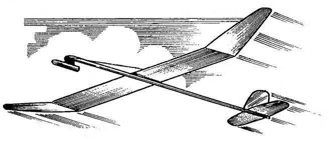
Fairing of the engine compartment carved from basswood and lightweight from inside. On the axis of symmetry of the wing from the bottom, glued the pylon variable thickness, the shape in plan which corresponds to the basic area on the fuselage. The thickness of the pylon in the front edge of the center section is 3.5 mm, rear—0.3 mm, which ensures the installation angle of attack of the wing 2°40’.
The stabilizer (A), Kiel (B), and the console of the wing (In).
At a distance of 7 mm from the leading edge is glued in the locking hook wire OVS diameter 0.7—0.8 mm. Considering that at the time of disclosure of the wing will have shock loads on the pylon, it is intensified by two bamboo pegs, fixed in the center section with epoxy glue. All hooks for attaching them to the rubber threads of the opening and the turn of the wing is made of wire, allied with a diameter of 0.5—0.6 mm.
Further, the center pylon of the wing, perpendicular to its lower surface, drilled 2 mm hole. Then the wing is installed on the axis (in planning), which fits missed Amalita celluloid washer and Teflon compensator, and then the entire package is tightened with a M2 nut until it is tight pylon wing of the court, and in such position it is left until the glue dries.
Automatic forced landing— wick, it consists of a pair of hooks of the mount rubber, balancer, textolite thermal protection and wick. The essence of his work lies in the fact that when pareige retaining bracket thread the rubber isolator converts the rocker for dimensions of the model, resulting in model rocket glider goes into kupirovaniya. The attachment of the wick shown in the figure.
If the model is prepared for the start of the wing is bent under the center section and is rotated counter-clockwise by 90°. Then nylon thread pounces on the hook for the wing pivot, the free ends are passed through the drainage holes of the engine compartment and fastened from the opposite side.
The model starts from the gas-dynamic setup. Its starting weight with the engine In-2-3 design of Yuri Gapon is 29 g. the Weight of the empty rocket is 18.5—20 g. the Specific load on the wing in planning mode about 5.3 g/dm2.
I. VOLKANOV, Dnepropetrovsk
Recommend to read
 KIRISKA – NO DEFICIT!
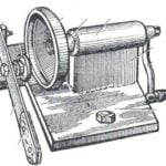
Something I have done for drawings and diagrams, published in the journal under the heading "Club home of the masters". In one of the rooms was a note on the machine to edit used caps...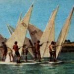 WINDSURFING: the prize of “M-K” — “Orbit”
We can safely say: all-Union competitions "the prize of the Heroes of the Cosmos" today, the most popular competitions of fans of Windsurfing. Last year, no" was attended by about 170...