“TEMP” IS GAINING SPEED

Immediately note: we offer avtomodelistov model Cordoba race car, neither in design nor the scheme is not a supernova. All solutions are individually well known, even not too experienced athletes. New design approach for decision models in General.
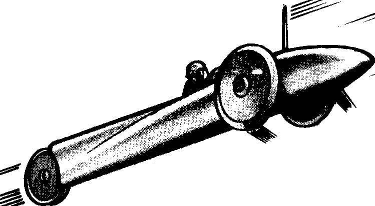
In the main features of the racing is extremely close to the common more recently, models-parcels “Temp”. Keeping the main thing the advantage of old circuits — direct transmission to the drive wheels, new micromachines modernize not only in appearance. The “Pace” even after a slight boost of the engine in most cases, delamination occurs, and reset the rubber wheels. The proposed option is provided with knife-like wheels, and this design, which not only excludes peeling “tires”, but at the same time and allows you to easily replace them in the selection of geometric and tverdostup characteristics of the rubber. “Temp” is a free layout and lightweight design (two punch from sheet aluminum, which formed the entire body, weighed very little). A new racing, on the contrary, very much diminished in size, but became almost twice as heavy. The meaning of both innovations is easy to understand. The first is aimed at maximum reduction of aerodynamic drag of the body, which is for the benefit and use of knife-like wheels to replace the old, wide, and the second, perhaps, deserves special consideration.
 
First of all, what affects the mass of the model? On a centrifugal load applied to the suspension system on the cords, the magnitude of the rolling resistance of the wheels to cover the tracks of the track at the wheel contact with the track and, consequently, the magnitude of the slippage, and finally, the level of vibration of the whole model. According to several publications in the “M-K”, the communication of vibrations from the wheel slip has become clear to all modelers, although still no reliable design data or experimental results. But the relationship of the shaking model and the clutch is undeniable. However, we are interested in more.
 
The main thing is to determine what the situation is on models of such a scheme for the reliability of torque transmission “through the wheel to the track”, what is the reliability of the clutch and, ultimately, how close transmission efficiency “wheels — asphalt” to the ideal.
Here not to do without at least simplified calculations. First we need to find the average motor torque at maximum power. This is easy to do using the formula:
 
N=M*n/716,2 where
 
N — motor power
 
M — motor torque, kgf*m,
 
n — frequency of crankshaft rotation, Rev/min.
 
Control line racing car with the engine working volume of 2.5 cm3.
Control line racing car with the engine working volume of 2.5 cm3:
1 — body-exterior, 2 — driving wheel, 3 — “the moustache” machine stop engine, 4 — canopy-cowl exit window of the cooling air and exhaust, 5 — keel protrusion of the body, the fairing of the rear wheels, 6 — rear (driven) wheel, 7 — motor, 8 — bearing unit of the engine system with the distribution of intake of the working mixture, 9 — cord strap.
 
After scaling, we find that, for example, are common amongst young athletes KMD-2,5, which develops maximum power of about 0.5 HP at 16-17 thousand rpm, the torque is equal to about 0,018 kg*m. After reduction of this magnitude to the radius of the wheel model will have the force with which the race “pushed” from the track with perfect traction. The calculation gives a value of about 0.3 kgf. A lot or a little (do note that this value is in principle the speed is not affected)? According to guides on automotive engineering, ordinary automobile tire might have a coefficient of friction with asphalt is 0.5. But this is a normal bus, and we have a knife-like rubber, though very hard; and not asphalt, and almost polished concrete track, often still partially oiled by the exhaust from the previously held models! Add to the above that in our case, model “shaker on wheels” is not even in comparison with the car which any such vibration completely blanked on only one resilient inflatable wheels, as will become clear in the clutch with the track of any safety cannot be and speeches! Even bringing the mass to the maximum permitted by the racing rules of values — 1.5 kg — do not give a full guarantee!
 
So, the “Temp” loses one point. Moreover, the engine it develops almost the same torque, but at low speeds. At the same time it turned out that the required maximum load of the model. By the way, it will give other positive effects. If rigidly linked to the main mass directly to the engine, will significantly increase its capacity while working on the model, will improve the mode and its stability. In addition, the weighting device will have the opposite impact on the loss of adhesion by vibration. After all, the bigger the node, the less the amplitude of the vibrations. So you can forget about the losses of rolling resistance weighted models, as the gains from increasing the mass much more.
 
Now to properly distribute weight along the length of the race. But for this first you need to specify its schema, to decide which axle will be leading. As seen, it is better to choose as a leading front axle. In an outright transfer it promises the greatest stability of the stroke (rear wheel constantly, regardless of external conditions, with little effort pressed to the track), and, as you know, for spinning wheels of considerable diameter remains such a “cocurrent” jet, what’s in it “sinking” any part of the body, together with mounted thereon the nodes. It is only important to ensure good flow around the front part of the model.
 
It remains to translate our findings in the specific design speed of the microcosm. But… try to do it yourself. After all, with the basic design principles you already know. And the orientation represent the look of the new Cordoba, calculated using modified Microdrive brand of KMD-2,5 (alterations mostly in the crankshaft and install the node of the second drive wheel, combined with the node of the distribution of the working mixture in the crankcase). The mass of the model, as already stated, equal to 1.5 kg, the direction of its travel on the track Assembly in a counterclockwise direction.
 
Of course, do not have to adhere to this particular development. You may be able to create a more perfect. Try! And when will be published the drawings “stuffing” of the model, you can compare your solution with ours and clearly identify the advantages and disadvantages of both. The only thing I would like to stop attention on the choice of gauge size. A small value is beneficial on two positions: reduced aerodynamic losses in the flow around a protruding bearing housing drive axle, as outside the body are only small areas, and it is possible at observance of all rules go to a rolling model only one master and one slave wheels (“motorcycle”) when you deliberately twisted cord strap. But too reduce rut is impossible. Otherwise, all winnings will be “eaten” a large increase of the resistance due to the gap between the body and wheels.
 
First two words recall what the problem was before avtomodelistov designers. This is to create the “crimped” in all sizes and weighted to the acceptable rules limit the machine under the engine type CMD, direct transmission to the drive wheels; was published the schema of an external view of the racing. Judging by the correspondence received by the editor from the readers, interested in this problem, the part of the modelers considered the problem insoluble, and the majority went astray assimilation of a new model of the technique of the masters. But attempts weighting due to the introduction of a powerful low case did not give the desired effect for additional loading (not milled the same low of steel!), and besides, the “smearing” of mass along the length of the machine harmful influence on the load distribution on the axles of the wheels. The rear driven axle was for a given model and given the engine is almost more loaded than the leading!
And the secret solution is extremely simple. It is only necessary in the beginning to escape from the magical influence of the knowledge champion “Mature” technology and… to completely abandon parts, functionally performs the role of the tool body. Remember, after all the positive properties of the new models should be fully displayed only if the concentration of mass in the area of the plant, and the load on the slave axis was set only by the reactive torque from operation of the engine. It is therefore clear: all additional weight must be located in front of the leading “bridge”! This is achieved by fabrication of a very compact bow heavy alloy, e.g. brass. Mounted on the crankcase such “blanks” is much simpler than either milled body and requires in the manufacture of high-precision machine tools. In addition to milling the rectangular groove under Carter and the simplest of details of the machine stops all processing of the workpiece size mm 40X40X80 (by the way, its weight is about 1 kg!) performed manually and presents no particular difficulty.
 
It is now clear that this decision opens the prospect to achieve the ideal center of the new machines may be exactly on the axis of the crankshaft of the engine. On this basis, the entire tail section should be designed is easy enough. If this happens, it will be possible at the same time and get rid of the worries on the suspension of the rear wheels.
 
Do note that in the present embodiment, is provided and effective cooling of thermally highly loaded crankcase of the motor.
 
There is another feature of the new scheme is “psychological”, which may not immediately appreciate found way of designing. Please note: this race no component that performs the role of the body, but in General the model does not need it! In fact, this machine is a compact and required of the mass “pulling” him for a fairing to the fuel tank and slave bridge. And in the race even at high speeds the tail is practically not loaded.
 
Now, when it became clear the main idea, let us look at some features of the car. Design finding can be considered automatic stop of the engine, consisting of two parts. So it works out. In shoulder-in “mustache” cut from steel sheet of 1.5 mm thickness, included in a semicircular hole in the valve cover of stravlivanie pressure from the crankcase (the engine is fed under pressure, such as the fuel supply was the most reliable for KMD). When shibani “mustache” shoulder slips out of the hole, although until securely holding the valve due to the elasticity of the rubber seals under the valve cover. Released as a result of the cap goes in the drilled channel in the brass nose of the model, opening a through hole diameter 4-5 mm. the Motor stops immediately, and remaining constantly lubricated by fuel, which is impossible when you stop using the compression or overlap the fuel line. The dimensions of the channel are selected so that the cover is not far from the landing nest valve. Then closed again it will be a simple turn of the “mustache” into position. The cover is useful to provide the guide shank. This will enable it to accurately samoustraniajutsia when you close the valve and will save you from making unreliable microcarriers suspension cover.
 
Design of racing córdoba in the box with the engine working volume of 2.5 cm3.
Design cord racing slot car with the engine working volume of 2.5 cm3:
1 — sock (brass), 2 — cord strap of standard size (steel) 3 — axis USA (wire Ø 2.5 mm), 4 — “the mustache” machine stop engine, 5 — valve cover (bronze, brass), 6 — sealing ring 7 — valve body (brass), 8 — pin additional fixing of rubber, 9 — ball bearing 8X16 mm, 10 — modified Carter KMD (except for trimming on both planes of the openings of the crankshaft, you want to produce grinding of the contact surfaces of the shirt of the cylinder to reject the latter and to Refine the bypass channels in accordance with channel shirt, turned to the exhaust pipe 180°), 11 — a standard cooling jacket of the cylinder, 12 — a wall-a bulkhead (plywood 3 mm), 13 — dugout fairing (black), 14 — fuel tank 15 — pipe filling the tank (before starting the engine to drown out), 16 — plate rear axle, 17 — fairing base (plywood 5-6 mm), 18 — axle rear wheel, 19 — tube guide key 20 — axle shaft-spool (steel 40X, cemented, kalit), 21 — insert the insert housing (D16T), 22 — nut insert, 23 — nut sliding bushing, 24 — slide bushing (bronze or Д16АТ), 25 — jet carburetor (MK-17″Junior”, modified), 26 — overlay threaded, 27 — 9X20 mm ball bearing, 28 bearing housing of the crankshaft (steel), 29 — a primary drive wheels (40H), 30 — modified shaft KMD, 31 — screw, 32 protection washer bearing, 33 — external ROM (40X) , 34 — rubber wheels, 35 — insert mate shaft regular KMD and bearing 9×20 mm (40X).
The figure shows the fastening cord trims on the option front.
 
Standard steel cord strap is attached to a brass wear arbitrarily. One option is a milling of the recesses in which the screws are attached subsidiary parts flush with the surface. By the way, this operation, like the final finishing of the socks, is best done only after complete Assembly of the model. So will be able to provide the desired mass of the model with excellent balancing.
The tail part is wooden. Dugout after the top mounts fit on a plywood base. The whole fairing is impregnated with a liquid parquet varnish and fixed on the model on the elongated studs used for mounting the motor on the toe. Plate rear axle thoroughly degreased by seal roughly machined surface of the tightly wrapped cotton thread and after impregnation nests and strands of fresh epoxy on it is glued into the fairing. It is useful to constantly control the position of the plate, so as later to rule the direction of the rear wheels will be much harder. (Rear wheel is common, maximum lightweight construction.) Do not forget to paste and guide for the new spetsklyuch adjust the degree of compression of the KMD. It is similar to the standard, only considerably extended. The fuel tank does not require special explanation, the main task is to provide a high reliability when working under pressure. In customized-to-engine fairing cut three entry window cooling air and one for output. The work ends with the gluing of the canopy fairing. Its main function is to create a high vacuum in the course model in the area of the Windows of the outlet of the cooling air and exhaust gases and thus to ensure effective cooling of the motor. So the air flow went down the shirt of the cylinder, and not “walking” in the cavity of the tank at the upper end of the head to attach the bulkhead-the bulkheads. This item, incidentally, will prevent further wooden dugout detail from cracking.
 
Special discussion deserve the power system. Considering that we managed to create a good model, we can safely say: everything else depends on the power and reliability of the host and the engine. Face it — the proposed revision KMD we do not consider it ideal because of some pereprodannosti in the area of the right axle shaft. Maybe someone will seem easier to milled afterwards new Carter or Carter are from “Temp”. However, in any case, we recommend to use a removable sleeve slip (we have it fixed with a nut at its outer end and studs on the collar, preventing the turning of the parts glued in and clamped with the nut dural insert in the nose of the regular Carter). The meaning of easy Dismounting of the sleeve is not in the replacement of worn parts. Because the load is negligible, as specially given of the bending of cord strap in the race car moving on one of the drive wheels (1), and therefore the resource right axles exceeds the resource ball bearings left. Most importantly — ease of access and dialog box intake fuel mixture, and perform additional pass-through Windows in the sleeve, reducing the contact area with the rotating shaft of the engine. The last is a very important factor in crossing. If you do not believe, we recommend you to test with two identical bushings, which differ only by the absence or presence of additional Windows. Ideal — when on the inner surface there are two “bearing” belt width 3-4 mm at the ends of sleeve yeah, the band around the window distribution of intake of the mixture for sealing the crankcase of a running engine.
 
The drive wheels are made of high quality steel. Made of anodized aluminum, oddly enough, in this scheme is less appropriate due to the lower stiffness. Part of the wheel, sitting down on the cone shaft modified KMD, needs to be performed particularly accurately. After the Assembly site is useful on the balancing stand to check the runout of the disk, and then remove it only when absolutely necessary. Replacement rubber ring is made simply by unscrewing the notched screw in the cut slot of the shaft, and removing the external drive wheel based on the diameter of the projection to the base disk. The outer carries a variety of zaccagnini micropiles that improves the reliability of clamping of the rubber, which on the mounting surface of both discs additionally protectives a series of small grooves. Execution threaded socket in the shaft KMD difficulty is not. After all, under the firm “crust” cieniowane or nitrided surface is quite soft steel. However, the most interesting and technically difficult path of making a new crankshaft without balancing cuts in cheek and designed specifically in relation to the shortened insert of Carter.
 
N. NIKOLAEV, the head of the circle

Recommend to read

  • OVERCHARGING THE BATTERY? Is ELIMINATED!OVERCHARGING THE BATTERY? Is ELIMINATED!
    One of the problems for the citizens-owners of vehicles is the condition of the batteries. Frequent stops on subsequent runs of the engine discharged battery, a full charge from an...
  • USE THE TOOTHPASTE? Wait a MINUTE!USE THE TOOTHPASTE? Wait a MINUTE!
    For polishing articles made from metal it is best to use special toothpastes — Krokus, GOI. I want to offer recipes for their cook. The first will need the iron sulphate is white...