 Offer simple design of gliders developed in the circle of experimental design. syut Kostroma. They are all made mostly of foam, but differ from each other in size, proportions, mass, manufacturing technology wing flight characteristics. Models are recommended for the manufacture of young modelers in the home, in group classes and the technology classes.
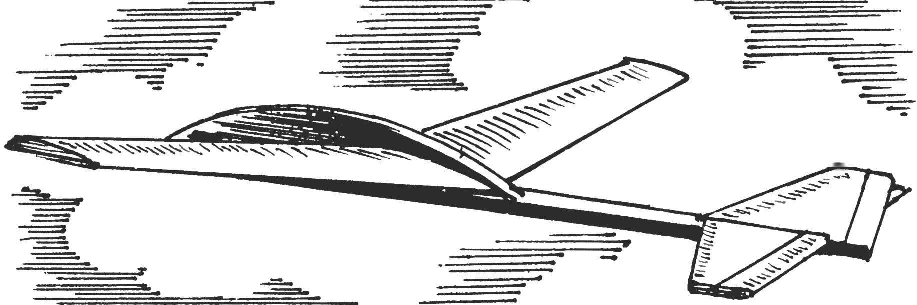
Small, light glider with a wingspan of 200 mm and weighing 4 g (Fig.1) belongs to the category of simple entertainment models and can be made in a few hours. His start in the sports hall with the hand, or in calm weather on the Playground using the catapult. Model with a wingspan of 230 mm and weight 7 g (Fig.2) slightly heavier and stronger, the duration of its flight is higher (about 15 seconds). The glider is designed to run with the hands and with the use of catapult (even with little wind) on a football or another field.
A more sophisticated model (Fig.3) with a wingspan of 400 mm and weighing 26 g is throwing the glider. Building throwing gliders enthusiastically engaged in both beginners and experienced modelers. In this class of models competitions. The main objective is to achieve maximum flight duration. The climb is provided only from the throwing hand. When designing this glider has to solve a complex task. It is necessary to achieve the optimal ratio of the mass of the model, the shape and area of load-bearing surfaces so that the airframe could throw at maximum height. After takeoff the model must clearly move to a stable long planning. To this end, in the proposed design of the nose of the fuselage is made sufficiently short, and the tail boom is long, but is lightweight and durable. At this aerodynamic design is nearly weightless and compact tail located outside the zone of turbulence from the wing and works effectively. Even in the absence of ascending streams of pupils 5 — 6 classes if done correctly the cast managed to achieve a flight duration of micropetala to 30 seconds. To run this model requires a field size not less than 200×200 meters, it is better for the city.
The preparatory work consists in implementation of drawings of parts in full size, producing patterns of the wing, stabilizer, fin and forward fuselage, the selection of materials. Need ceiling foam tiles are 3.5 mm thick with dimensions of 500×500 mm (sold in stores of building and finishing materials), dense varieties of foam, wood (spruce, pine, Linden), PVA glue and paint.
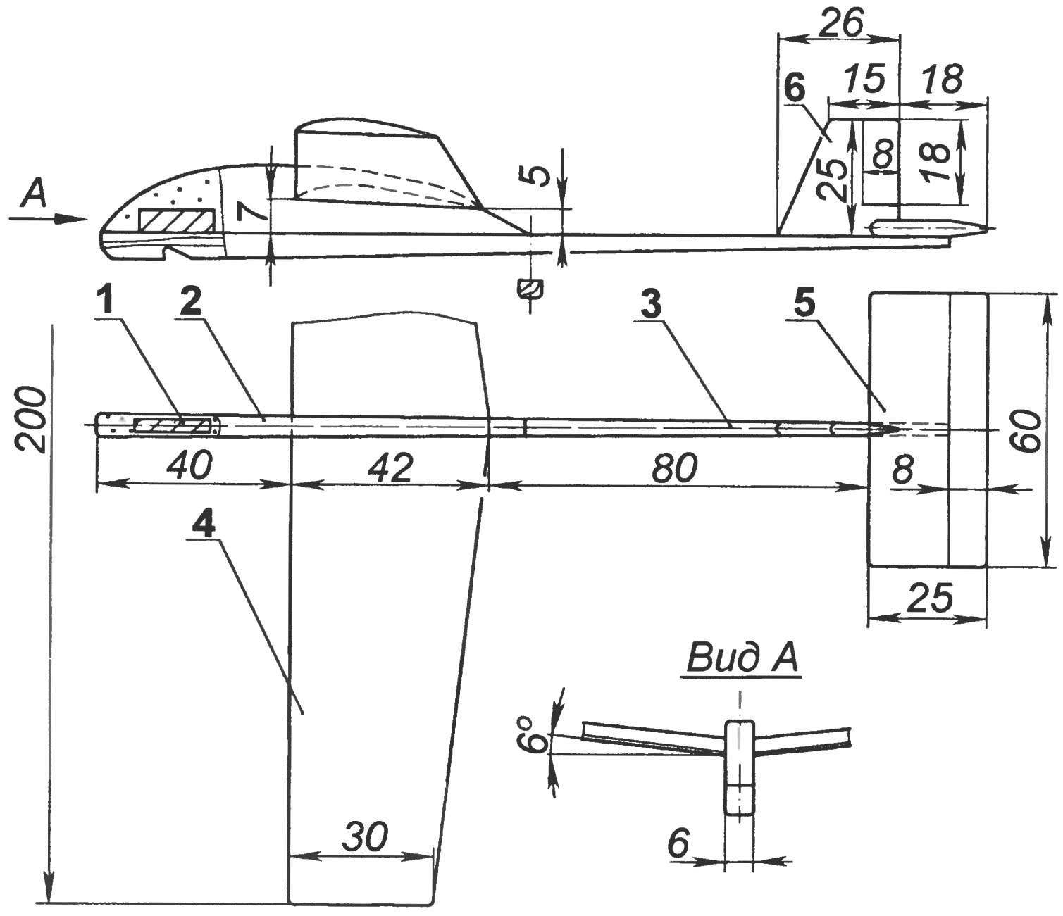
Fig. 1. The simplest entertainment model easy glider:
1 — centering weight (lead); 2 — the nose of the fuselage; 3 — fuselage (pine); 4 — wing; 5 — stabilizer; 6 — keel; material of parts 2, 4, 5, 6 — foam
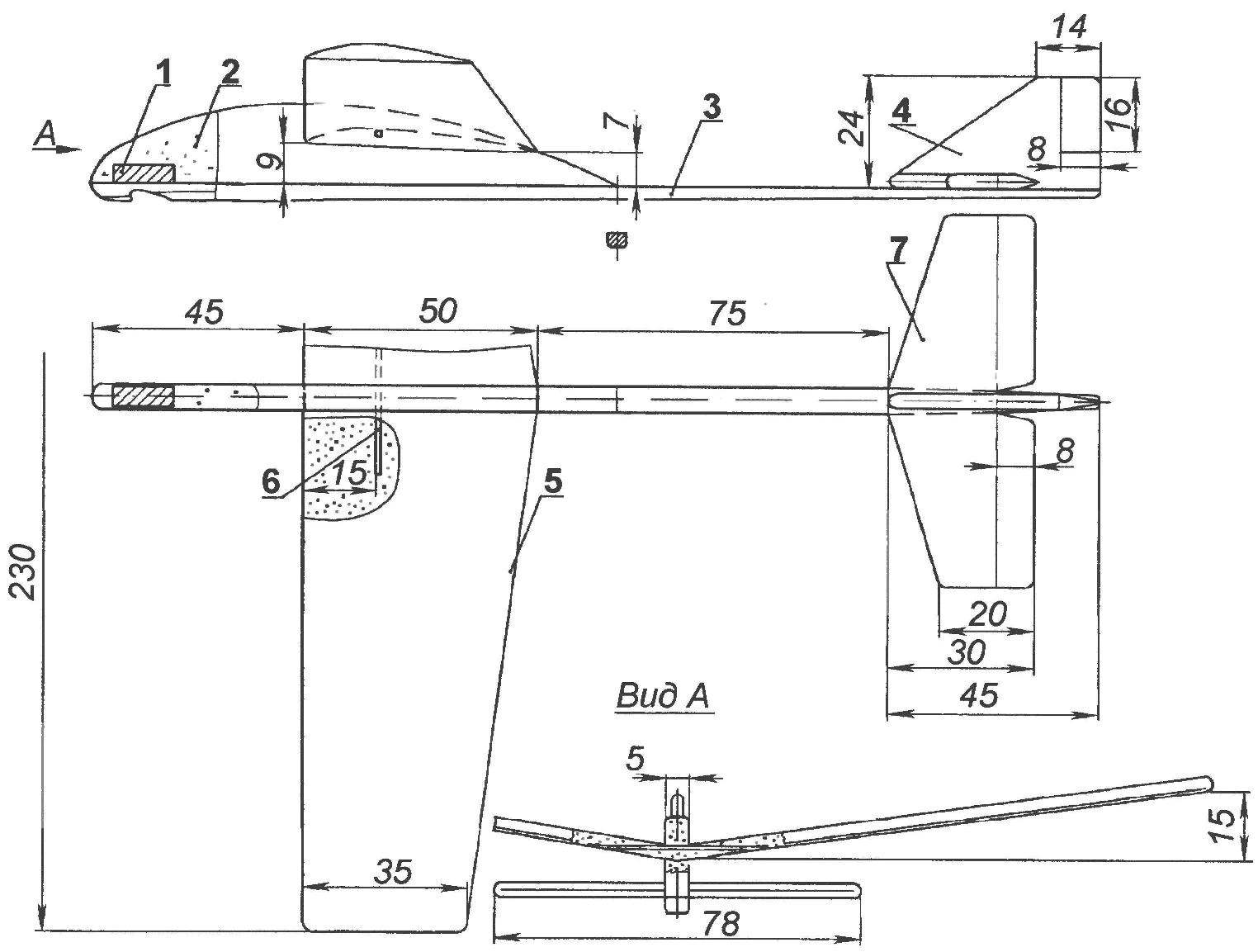
Fig. 2. Model glider to start with the hands and using catapults:
1 — centering weight (lead); 2 — the nose of the fuselage; 3 — fuselage (pine); 4 — keel; 5 — wing; 6 — spar (match); 7 — stabilizer
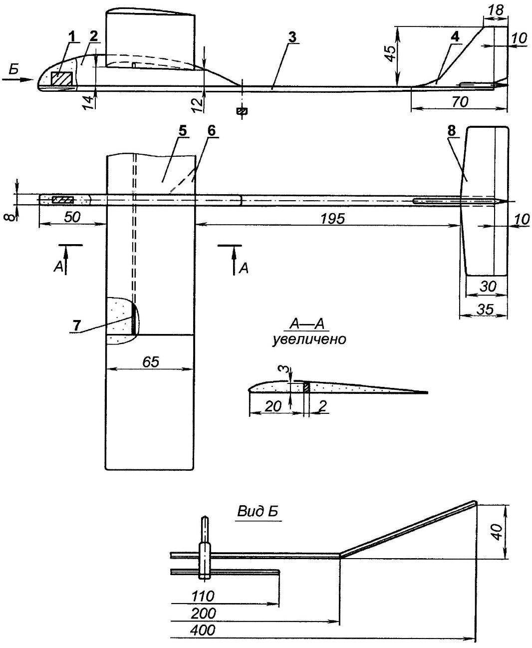
Fig. 3. Model throwing a glider:
1 — centering weight (lead); 2 — the nose of the fuselage; 3 — fuselage (pine); 4 — keel; 5 — wing; 6 — strengthening the pin (plywood s1,5); 7 — spar (pine); 8 — stabilizer
The creation of models it is recommended to start with the manufacture of the wing, fin and stabilizer. These parts after partitioning the contour template can be cut out with a scalpel. You should then proceed to their profile. In order to simplify the design of the wing across the span has a PLANO-convex profile. Much of the material from the line of maximum thickness are better off with a sharp knife. The finishing of the surface by using sandpaper of different grits glued to a plywood plate approximately the size of 50×200 mm, at a constant control on templates. To make the wing model (Fig. 1,2) a small transverse V-shape before gluing it into the slot of the fuselage on the axis of symmetry on the top surface to be cut. In the second of the proposed structures of the Central part of the wing is reinforced with a short spar of the match. In the model of missile airframe (Fig.3) on the lower surface of the wing should make a slit and glue it to the spar. Further from the wing where the spar ends, you need to cut the “ears” and re-glue them at the required angle. Pre-butt mowed down the surface of the skin so that the gaps were minimal.
As we know from practice start throwing gliders, a good shot is obtained when the fuselage is captured by the thumb and middle finger, and the last bend the forefinger rests on the back edge of the root portion of the right console. The lower surface has to be strengthened plywood or cardboard a 1.5 mm plate under the index finger. The front edge of the wing can glue a thin colored paper on the liquid PVA. Stabilizer and fin models have a profile of the “flat Board” with rounded edges. The incision should be allocated to the “rudder” and “Elevator”.
The nose of the fuselage models are made of dense foam, and the rake of the fuselage is made of light wood. In the bow made the slot exactly with the wing profile and the drilled cavity under lead weight. The exact location of the groove on the lower surface of the fuselage for engagement with a rubber cord of a catapult is determined experimentally.
The connection of the parts is carried out on the PVA glue. The wing is gently inserted into the slot of the fuselage and secured with glue. The junction of the wing and fuselage should be reinforced with strips of drawing paper. Next, glue the stabilizer and fin.
Trim models include the color nitroenamels slats of the fuselage and covered with paper plots of the wing.
Debugging gliders begin to eliminate bias, and then proceed to balancing. The center of gravity of the models that are launched using a catapult (Fig. 1,2) must be at a distance equal to approximately 33% of the width of the wing, counting from the junction of the leading edge with the fuselage. From missile airframe alignment of approximately 45°. Adjustment is an increase in the mass centering of the cargo or its reduction by drilling.
During trial runs of the models due to minimal deflection of the rudder pitch and direction to achieve a smooth transition after lift-off to hover in a left turn. Recommendations on how to run and debug the simplest, as well as throwing gliders previously disclosed in the journal.
TIKHONOV, Kostroma
Recommend to read
 TO CHARGE OR CHANGE?
The device was created to check the capacity of Nickel-cadmium and Nickel-metal hydride batteries, but they can check for any small capacity batteries and dry cells. The device is...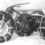 FOR ANY SOIL
Thanks to the "Modeller-designer" I'm still at school became interested in technical creativity. Three-wheeled all-terrain vehicle is one of my latest designs. It used the engine from a...
