
 Now, when the rules of the FAI, the weight of the rubber motor is reduced, and the number of rounds in the competition increased to seven, rotor group should be given maximum attention. Since modelers prefer to make the screws using two patterns: top view and side view. For two-bladed propeller made from a block of wood or plastic, more reliable way, perhaps, ever.
When it comes to rezinomotornaya models where the large diameter screw consists of two separate blades fixed to a hinge sleeve, this method is not efficient: it is of great complexity, and many valuable timber — balsa is wasted. In addition, when working with two patterns easy to make a mistake. In the result, designed characteristics will be distorted and will decrease the efficiency of the propeller. In the manufacture of individual blades rezinomotornaya the model we recommend to apply the described below technology.
For tracing the template and screw it is necessary to know its diameter, relative pitch, the shape of the blade in plan and profile sections. Currently, modelers use screws Ø 560-600 mm with a relative step of 1.15 and 1.5. To reduce the aerodynamic drag of the blades is given in terms of elliptic form. The greatest width is located at 60— 70°/on the length of the blades and is equal to 8-10% of the diameter of the screw. The cross section of the blade profile: convex-concave (the amount of concavity not more than 2 mm).
For geometric construction will take the screw diameter is equal to 580 mm, the relative step — variable; maximum h1 — 1.25 at a distance of 62% of the length of the blade, decreasing to the end of the blade to h2 to 1.08 and about the sleeve h3 is 0.86.
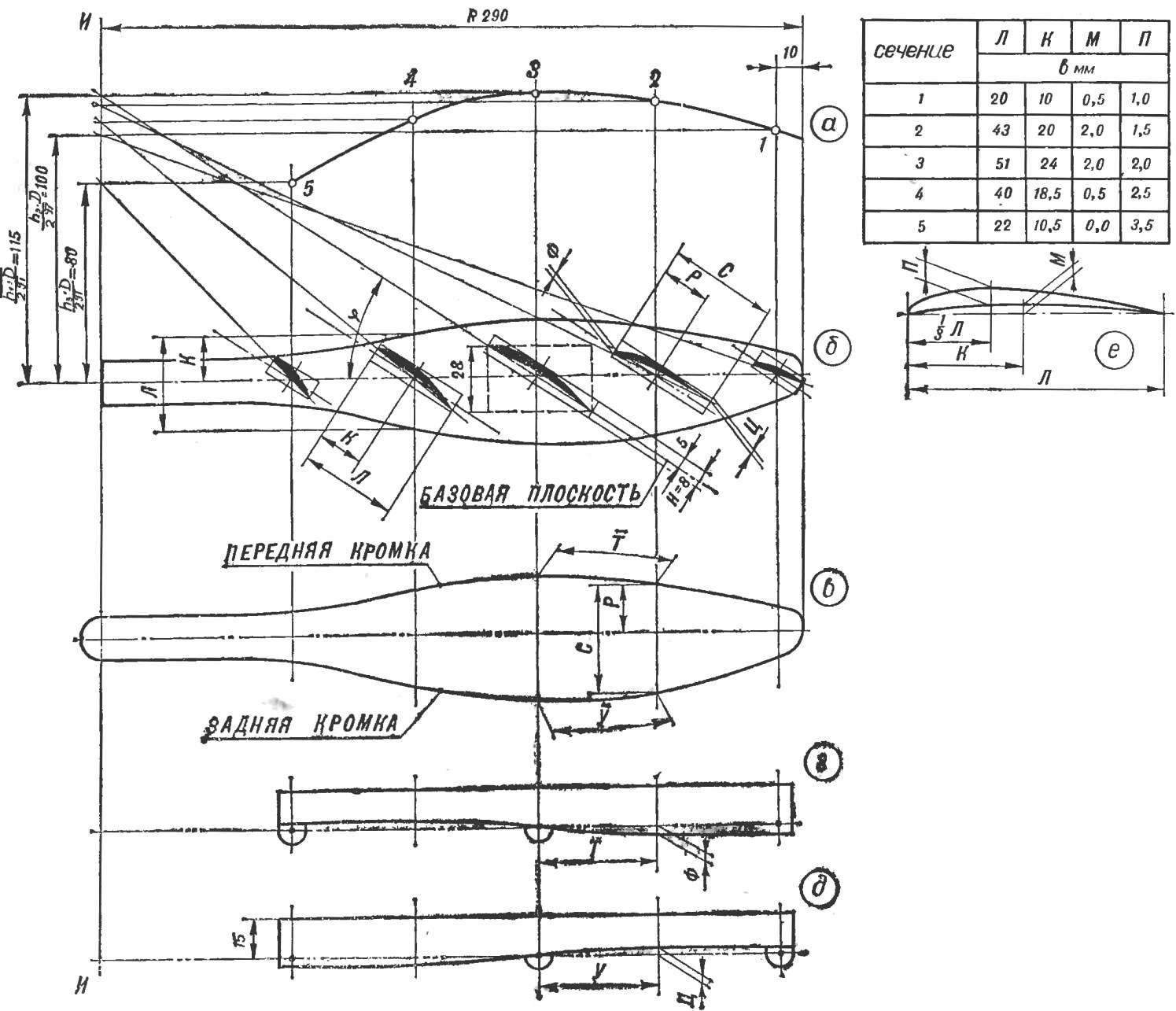
Fig. 1. Build templates for the rational procurement of screw:
a – change curve of step; b — scan of the blade; in — build template “top view”; d — construction template “side view” of the front edge; d — construction template “side view” of the rear edge; e — table of dimensions of the blade profiles and cross-sections.
To draw the blades take half of a sheet of drawing paper. On the left draw a vertical line AI (Fig. 1) is the axis of rotation of the screw, perpendicular to it the dash-dotted line — axis of the blade (Fig. 16) where you put the radius of the blade R = 290 mm.
Departing from the end of blade 10 mm, cross axis vertical lines at a distance of 50 mm from each other. These lines are called cross sections of the blade. To obtain a template of the screw the required accuracy of the cross section should be placed approximately 25 mm (because of the saturation of the picture intermediate sections conditionally ke shown). Choosing the maximum width and shape, will watertite sweep of the blade. In figure 16 it is depicted on the dimensions given in the table (Fig. 1E). On the line AI of the axis of the blade put up quantities of the three steps of the screw divided by 2π, i.e.
h1D/2, h2D/2, h3D/2π.
The ends of these segments draw a horizontal line to the intersection with the cross sections 1, 3 and 5. Plotting points join with a smooth curve (1, 2, 3, 4, 5), which is a change curve of step (Fig. 1A). Points 2 and 4 move to the line AI.
From the cut end h1D/2π in the point of intersection of the axis of the blade section 3 guide drawing a line in the beam. Similarly, connect the other blade section. The angle between each beam and the horizontal line is equal to the angle of inclination of the blade in this section. Putting aside for the respective rays, the width of the blade, watertite her profile.
Figure 16 shows the profiles constructed according to the dimensions given in the table in figure 1E. For thin lightweight balsa propeller blade weight of about 5 g.
To build a template of the screw, it is necessary to determine the position of the so-called reference plane. Its inclination to the horizontal select empirically so that the height of the workpiece N was the smallest. To this end, through each section guide reference plane (dash-dotted line with two dots) and around the profile, describe the rectangle with large sides parallel to a reference plane. Choice tilt the latter takes very little time, as it is usually equal or close to the slope of the rays in the middle of the blade. In the present case, this angle equals the angle of inclination of the beam passing through the section 3.
The above builds a certain minimum cross-section dimensions of the billet, one blade: width — 51 mm, height 8 mm (see section 3, Fig. 1B). The length of the billet model airplanes chooses for design reasons— it is equal to the radius of the blade or less.
Now start to build the templates. Sweep the blade steel, so you need to draw three templates: one top view and two side view (the front and rear edges). Spend three horizontal lines. On the top construct a template of the top view, what are the dimensions R and C, taken from section 2 (see Fig. 16) parallel to the reference plane, shift on the same section of the template. Do the same with all the other sections, then the resulting points draw a smooth curve (Fig. 1B).
On the middle horizontal line is the reference plane, build a template of the side view of the leading edge.

Fig. 2. The use of templates.
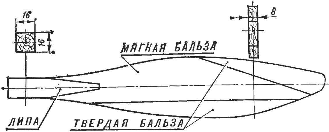
Fig. 3. The combined workpiece.
Since the front and rear edges of the template top view curved, and its maximum width is located on section 3, this type and should take over the centerline to build templates of the side view. Section 2 will receive a transfer curve of size T (Fig. 1B) on the template side view (Fig. 1G). Further, the size of f from the reference plane to the front edge profile in cross section 2 (Fig. 16) move to the appropriate section of figure 1G. did the same with all the other points, which then connect with a smooth curve. Similar make and build on the template of the side view of the trailing edge (Fig. 1D). The curves of both the patterns transferred onto the workpiece, form the lower surface of the blade.
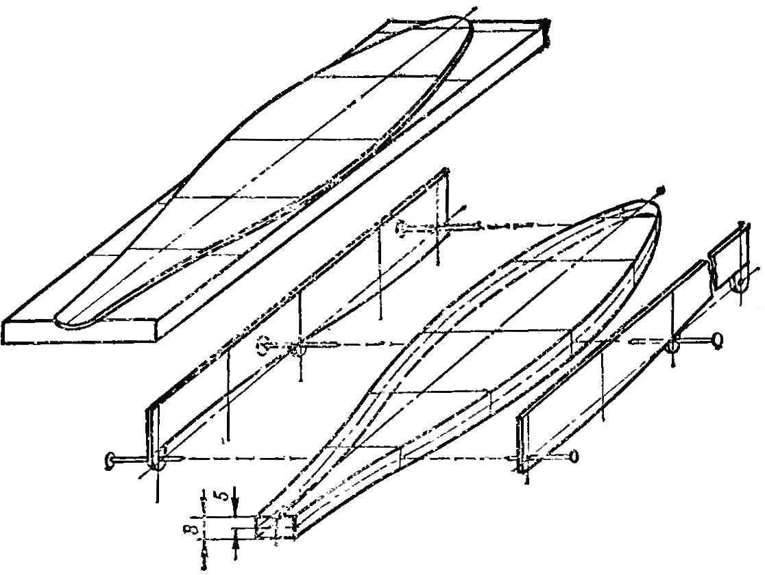
To templates were easy to use, their height should be at least 15 mm, and in three sections (1, 3, 5) it is necessary to provide the lugs. All templates are best made of thick paper or thin celluloid with a thickness of 0.5 mm. How to use the templates shown in figure 2.
Application template top view is self-explanatory. When working with types the side on the end surface of the workpiece, is cut along the contour pattern of the form above, we need to strike a trace of the reference plane (dash-dotted line with two dots) and cross the vertical planes. Then stationery pins in sections 1, 3 and 5 followed by a template and sharp pencil, draw the curves of both templates.
Further processing of the workpiece (Fig. 3) is performed as usual. The finished blades are mounted in sleeves at an angle to the plane of rotation of the screw.
The proposed method of construction and the manufacture of the blades has a number of advantages: saving of wood (the height of a rational procurement of 8 mm, and the conventional — 28 mm), reduces the complexity, furthermore, the screw has better aerodynamic qualities and is much stronger. Increased strength is achieved by using a combination of blank blades, thin front and rear edges of which are reinforced with solid balsa, and the butt is made of basswood. The shape of the blade ensures a good fit it to the round fuselage that reduces the overall resistance of the model.
P. KARZOV, engineer, master of sports
Recommend to read
 FLYING AT A HEIGHT OF INCHES
In the Soviet and foreign scientific and popular journals have repeatedly reported Nicoleta apparatus-ekranoplan, including the Soviet pilot the rescue boat amphibious ESKA-1. This car... TABLE-“CENTIMETER”
Many of the works performed on the bench — not the table — associated with the need to check the dimensions. But in many cases far more convenient to do without these devices, it is only...
