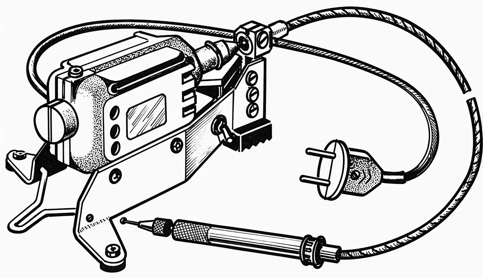
For most people, mentions of a dental drill bring unpleasant feelings. But for a skilled craftsman the attitude toward this equipment is different. Perhaps only this mechanism makes it possible to machine complex surfaces and hard-to-reach places in contoured parts. That is why, among other necessary fixtures and equipment, an electric rotary tool (dental drill type) will not be out of place in the arsenal of a home workshop.
Structurally, a hand-held “electric mill” (as technicians more often call a dental drill here) consists of an electric drive, a flexible shaft, and a control handle in which the tool is clamped.
The drive used for the rotary tool is an MSH-2 electric motor intended for household sewing machines of class 2M-4.
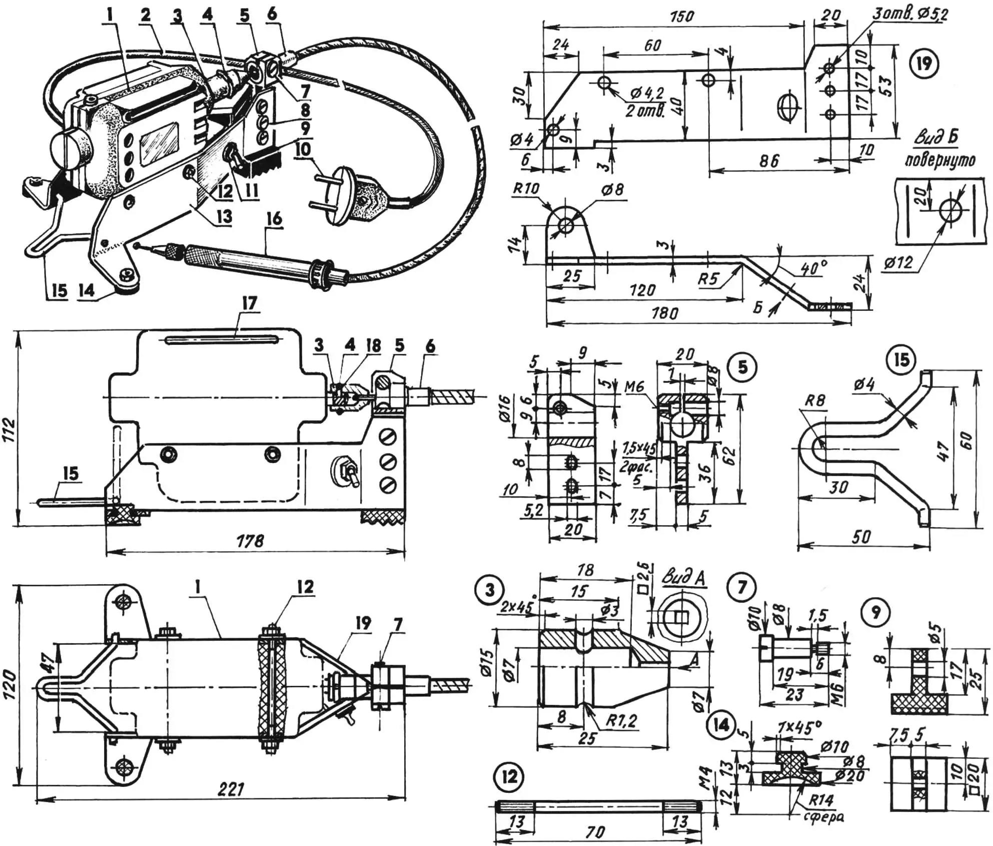
1 — electric motor MSH-2 (from a sewing machine); 2 — power cable of type PRS (wire cross-section 1.5 mm2); 3 — adapter bushing (steel 45, round bar Ø15); 4 — spring ring retaining the half-pin (spring wire Ø1.5); 5 — bracket (St3); 6 — flexible shaft in a Bowden sheath with end bushing and union nut M18x1.5 (from an MMVZ or “Izh” motorcycle); 7 — special screw M6; 8 — bolt M5 with spring washer (3 sets); 9 — front rubber support; 10 — power-cable plug; 11 — toggle switch TP1-2; 12 — stud M4 with spring washers and nuts (2 sets); 13 — right longeron (St3, sheet s3, 2 pcs.); 14 — rear rubber support (2 pcs.); 15 — hanging bracket (spring wire 04); 16 — handle; 17 — clamp M4 with spring washers and nuts; 18 — half-pin; 19 — left longeron
(item 17 is not shown in the top view)
The motor is fastened to a base made of two longerons by a pair of transverse M4 studs with spring washers and nuts, installed instead of the stock clamp with the same thread. The base is three-point supported. The supports are rubber: two identical rear ones are inserted into holes in the longeron extensions at the back, and one front support is fastened between the longerons at the front. Here, only higher up, a supporting bracket for the flexible shaft is fastened with two M6 bolts; the shaft is a steel cable in a Bowden sheath. The flexible shaft is taken from the speedometer drive of an MMVZ motorcycle (one from an “Izh” motorcycle can also be used). The supporting bracket has a clamp terminal in which the end bushing of the sheath is secured. Moreover, the clamping bolt in the terminal acts both as a stop (it keeps the bushing from jumping out of the clamp even when the flexible shaft is pulled during work) and as a retainer (it prevents the sheath from rotating when the flexible shaft turns).
Torque from the electric motor is transmitted to the flexible shaft through a homemade adapter bushing mounted on the motor output shaft, where it is fixed by a half-pin; and the latter (so that it does not fly out) is covered by a springy ring. A square hole is made in the end face of the bushing, into which the tip of the flexible shaft with a matching square cross-section is inserted. The other end of the flexible shaft is inserted into the same kind of square hole in the tip of the handle shaft and is fixed by the sheath union nut screwed onto the handle housing (not shown in the drawing).
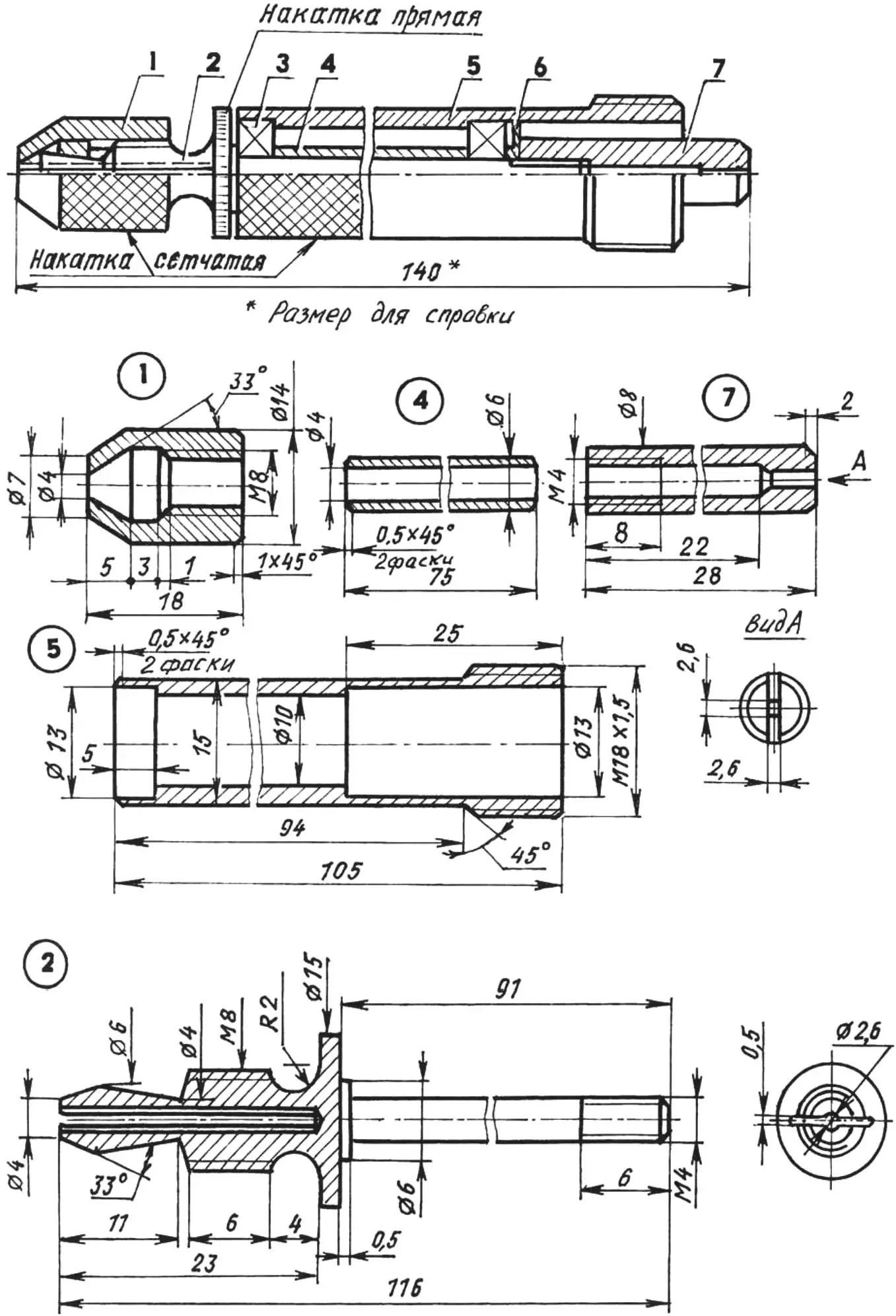
1 — sleeve (steel 45, round bar Ø14); 2 — handle shaft (steel 45, round bar Ø15); 3 — bearing No. 24 (2 pcs.); 4 — spacer bushing (St3, tube Ø6×2); 5 — handle housing (St3, round bar Ø18); 6 — deflector washer (capron); 7 — shaft tip (steel 45, round bar Ø8)
The handle shaft is made as one piece together with the collet (a split spring bushing), into which a bur or another machining tool is installed and secured with a clamping sleeve (the inner cone of the sleeve matches the outer cone of the bushing).
The shaft in the handle housing is mounted in two ball bearings No. 24. The bearings are lubricated with grease (for example, litol) packed into the handle cavity between them. To keep the grease from flowing out of the cavity during operation and to keep dust from entering the cavity, bearings with two shield washers are used, and an additional fluoroplastic oil-deflector washer is placed in front of the tip.
Installing and removing a tool in the collet chuck is done the same way as in a hand drill, without using a key. When unscrewing and screwing the sleeve, both the shaft flange and the handle must be held against turning at the same time. For this purpose, knurling is applied to the outer cylindrical surfaces of all parts: a diagonal cross-hatch on the handle and sleeve, and a straight longitudinal knurl on the flange.
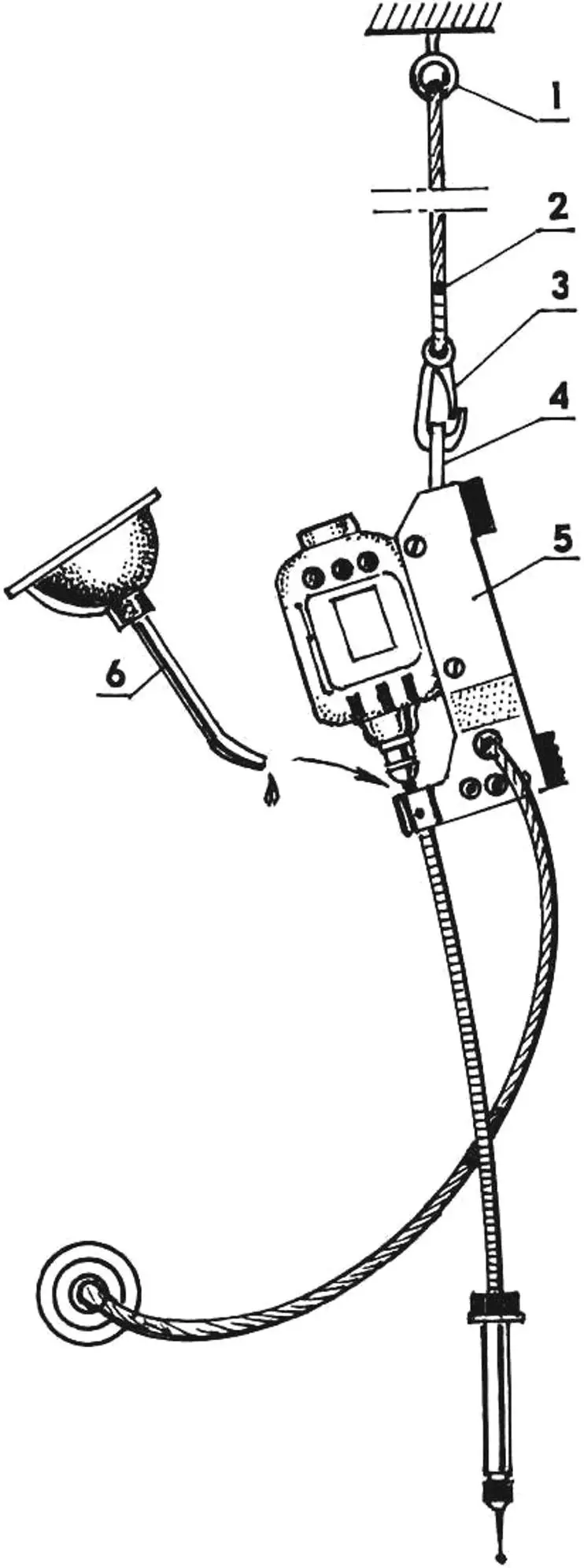
1 — hook; 2 — strap; 3 — carabiner; 4 — bracket; 5 — rotary tool; 6 — oil can (before work, apply 3—4 drops of oil M12GI or M12G1)
It is not always possible to find a suitable tool for the rotary machine. Therefore, much of what may be needed makes sense to make yourself. For example, decent cutters can be obtained from broken drills by forming the required profile on a “grinder” (a sharpening machine with an abrasive wheel). And from fragments of medium-hardness abrasive wheels, decent grinding heads can be made. First, a seat hole 2.6 mm in diameter is prepared in the fragment with a carbide or diamond drill. An arbor of steel wire 2.6 mm in diameter and 30 mm long is bonded into the seat with epoxy adhesive. After the adhesive hardens, excess protruding edges of the stone fragment are removed on the grinder with a coarse-grit hard abrasive wheel. The final surface of the grinding head is formed with a carbide tool.
To change the rotational speed of the cutting tool (which corresponds to the motor shaft speed), a starting/regulating carbon rheostat is introduced into the motor supply circuit. The rheostat is a stock one from a sewing machine. It makes it possible to change the shaft (and tool) speed practically from several dozen to 6000 revolutions per minute. If no rheostat is available, the motor is connected to the mains through a toggle switch brought out to a longeron (left or right — whichever is convenient for the craftsman, depending on whether he is right- or left-handed). Naturally, the speed can no longer be changed in this case, and it will correspond roughly to the motor’s rated speed — about 6000 rpm.
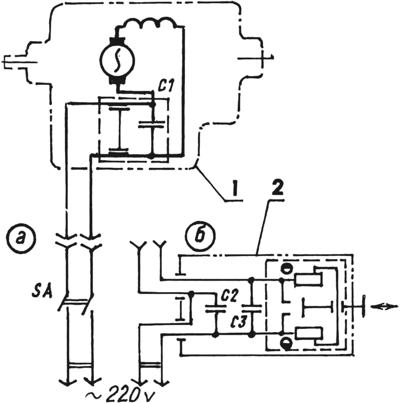
1 — electric motor; 2 — carbon rheostat (from an electric sewing machine); C1 — motor capacitor bank; C2 — KBG-I — 0.05 µF (400 V) and C3 — MBGP-1 — 0.5 µF (400 V)
The power cable is of type PRS with a wire cross-section of 1.5 mm2. The cable is brought in through a hole in the longeron and an insulating protective capron bushing on the side opposite the toggle switch.
The main working position of the rotary-tool drive is resting on the rubber dampers. However, when the “flexibility” of the flexible shaft is insufficient, to compensate for this shortcoming the mechanism is hung in a vertical position on a hook in the ceiling (or on a strap with a carabiner if the ceiling is high). In the same position, before each use the flexible shaft is lubricated with a few drops of machine oil M12GI or M12G1. For hanging the rotary tool, a movable bracket of springy steel wire is inserted into holes between the longerons behind the electric motor. The electric mill is also stored hanging on the wall.
Electric motor specifications:
supply voltage, V … 220
— power consumption, W … 40
— rated current, not more than, A … 0.5
— rotational speed, rpm … 6000
— duty cycle … intermittent short-time
“Modelist-Konstruktor” No. 8’2005, V. PETROV
Recommend to read
 GLASS CUTTER WITH COMPASS
To cut a round hole of large diameter, to make a glass disk or a ring will help this simple tool. It consists of three parts. The dimensions of the steel rod Ø 5 mm depend on the... THREE-PHASE — IN HOME NETWORK
"For the treatment of infield has decided to replace the tiller internal combustion engine electric. Already got polutoraterabaytny the motor. But it is three phase. How to connect to...
