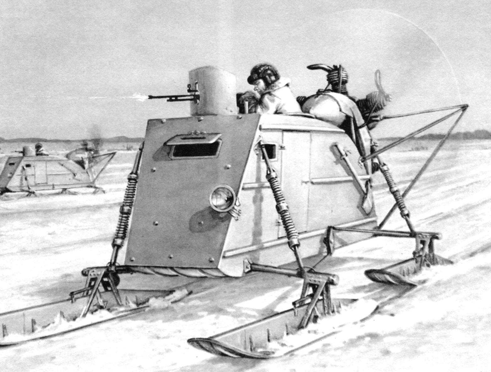
 The NKL-26 was designed to carry a crew of two people – the commander of the machine (while running in combat operations of the function arrow) and a driver-mechanic. The body of the snowmobile hardwood, closed type, with four independently suspended steerable skis. The frame is recruited from transverse frames and longitudinal stringers and trimmed with plywood. The cross section of the body had the appearance of an inverted trapezoid. The front part defended fortified at an angle of 60° to the vertical armor plate shield. In it there was a hatch with a flap, which made a narrow slot.
The only door was located to the left, parallel to the driver’s seat, on the sides there were two small Windows for side view.
In the compartment of the commander of the snowmobile in the roof, there was a round hole, equipped with reinforced edging. The trim ring is attached to the base on which was mounted a turret for a machine gun DT 7.62 mm Turret had an armored shield with a notched cutout for the gun. The rotation mechanism is provided horizontal angle 300°; 60° were in the area of the rotating propeller.
In the rear, with the commander’s compartment housed the petrol tank.
The chassis of the snowmobile consisted of four equal size skis, axles and struts.
Ski open, T-shaped cross section are interchangeable. The front part is wider than the rear, thereby reducing the lateral friction when driving on loose snow. They are made of wood, sole – out of 10 mm plywood, the longitudinal edge of the pine boards. Mount three pairs of angular steel brackets, rack of wild boar and all – steel gusset plate.
Axles were made of steel thick-walled tube. On the outside, the Bush pig was welded lock ring and lugs for connecting the traction control and suspension struts. The attachment of the rod to the body was performed on the universal joints.
Spring telescopic strut was very effective.
Control of the snowmobile was carried out using the steering wheel mounted on the axis of the machine in the driver’s cab, through a system of ropes and levers. Spin the wheel to turn simultaneously all four skis, which dramatically increases maneuverability. On the steering tube was placed a drum for reeling the cable. From him the cable through the guides located on Board and on the hull floor, reached for the rollers on the lever of the main shaft.

Transport NKL-16

A layout diagram of the NKL-26:
1 – front ski, 2 – axle shaft; 3 – body; 4 – headlamp lighting; 5 – armor plate; 6 – inspection hatch; 7 – fold hatch with a gap slot; 8 – ring turrets; 9 – machine gun; 10 – armored shield on swivel turret; 11 – main fuel tank; 12 – fuel tank inlet; 13 – engine struts of the frame; 14. power plant; 15 – reserve fuel tank; 16 – removable oil tank; 17 – magneto ignition; 18 – propeller; 19 – exhaust pipe; 20 – thruster; 21 – under engine frame; 22 – starter; 23 – heater air inlet to the carburetor; 24 – fencing of the propeller; 25 – rear strut; 26 – rear axle shaft; 27 – ski pylon; 28 – brake mechanism, 29 – rear ski; 30 – battery 31 – control rod, rear; 32 – tape fastening of a petrol tank; 33 – tool tray tank; 34 – fry-in-chief of the control shaft; 35 – control rod, front; 36 – cabin door; 37 – strut; 38 – bearing axle

NKL-26, overall layout

Shock romance:
1 – the unit of the shock absorber housing; 2 – ball tip stationary tube absorber; 3 – spring; 4 – the bottom of the movable pipe of the shock absorber; 5 – node of attachment on the axle
The main shaft was installed on the floor of the cabin on two pillars. To reduce stress on the rim of the steering wheel in a system of cables introduced double block. On the main shaft mounted oneplace lever with the rollers on the column head. The cables passed through the unit and swinging the roller in the rear part of the housing. On the main shaft outside of the machine secured duplica bipod, connected by rigid tubular rod fork threaded lugs connecting the bipod with the axes of the suspension skis. To ensure simultaneous rotation of the skis in different directions, the coupling rods to fry the main shaft was carried out as follows. Right traction control front ski is connected to the upper eyelet drying, and right rear pull on the lower eyelet. The left hand switching was carried out in the reverse order.
In front of the driver was the instrument panel.
The installation of the engine NKL-26 are similar and interchangeable with the NKL-16 (see “M-K”, 1977, № 10). Engine M-11 G had five star located in one plane of the cylinders are air-cooled. On the engine before installing the snowmobile to run from the driver’s seat additionally put an electric starter and generator. Their place – the left and right outer sides of the lower cylinders.
The engine is matched with another unit – heater air inlet to the carburetor (see “M-K”, 1977, № 10). The installation of improved engine performance at low temperatures, eliminating the impoverishment of the working mixture flowing into the cylinders, and freezing suction channels and a carb. The air heater was a cover, attachable flange to the carb. Within the housing passed the exhaust pipes of the two lower cylinders of the engine. At temperatures below -20° at the housing is additionally pulled a heat insulating cover.
Exhaust pipes the top three individual cylinders, the ends of the tubes had slanting cuts, located at a counter stream of air. Due to this, when driving the snowmobile was an intensive suction of the exhaust gases.

Control scheme:
1 – rear axle shaft; 2 – cardan joint; 3.19 in – unit sealing control cable; 4 – the adjusting threaded coupling; 5 – movable roller; 6 – control rod; 7 – timer; 8 – control rod left front ski; 9 – block rocking rollers main shaft; 10 – steering wheel; 11 – a drum for winding the cable; 12 – block side rollers; 13 – the case of the snowmobile; 14 – mount shock absorber-to-axle; 15 – hog the front of the ski; 16 – control rod right front ski; 17 – control cables; 18 – block the rollers; 20 main shaft; 21 – the lever of the main shaft; 22 – control rod right rear of the ski; 23 – the adjusting plug

NKL-26 division captain Profatilova with troops Tommy goes to the starting line. District of Novgorod, 1944

Model NKL-26

The instrument panel and placement of controls:
1 – ignition switch; 2 – button starter; 3 – the petrol gauge; 4 – steering wheel; 5 – air three-way valve; 6 – oil thermometer; 7 – ammeter; 8 – oil pressure gauge; 9 – the switch of headlights; 10 – starting magneto; 11 – tachometer; 12 – the brake pedal, the rear of the ski; 13 – gas pedal; 14 – brake pedal the front ski; 15 – air pump Drawings developed on archival materials engineer I. Usenaliev and performed artists K. Koval and M. Linde
The engine was fixed on the under-engine frame bolts through cushioning and absorbing harmful vibrations of the sleeve. At the bottom of the frame ended with two fork lugs that secure it to the lugs of the power units of housing. The front (in the direction of the snowmobile) to the ring frame was welded two more pairs Ushkov – for screed resistant struts, providing rigidity of attachment.
The front part of the plant supplied with the hood, a streamlined shape, fastened to a ring motor frame. The top flap on two hinges. Under him were the main reserve petrol and oil tanks. The main fuel tank was located in the rear of the hull on a special cradle, which was fixed with steel tapes.
The shank of the crankshaft, an intermediate part – sleeve – mounted two-bladed wooden propeller. Its blades at the ends and working edge had metal fittings. Bushing screw seated on the tapered shank of the crankshaft in the keyway and tightened the special nut; avoid spontaneous loosening it must contries wire.
To ensure the safety of the zone of rotation of the propeller was protected by a tubular metal fence, covered with bright red paint.
I. USENALIEV


