
I have been subscribing to the magazine “Modelist-Constructor” for a long time, almost since its very beginning; I have gained a lot of useful knowledge from it.
Responding to your call to be not only a reader but also an author, I decided to write about my experience in making chain-link mesh. The method itself and the device are so simple that they are available to anyone who would like to fence a summer cottage, build a bird aviary, a cage, or an enclosure for other livestock.
Of course, nowadays almost any material can be bought in stores, but another type of shortage has appeared — money. With the proposed technology, you can even work with wire scraps. At one time, I looked through a lot of literature and found nothing but general diagrams. Therefore, I had to figure out a lot in practice. I hope my experience will be useful to someone.
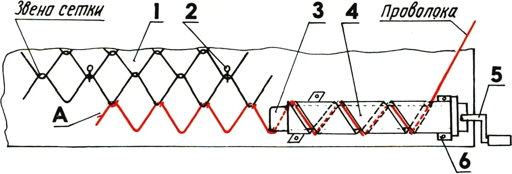
1 — table; 2 — pin; 3 — wire winding knife; 4 — cylinder-step former with spiral slot; 5 — handle; 6 — bracket.
A — front end of the wire.
For making chain-link mesh by hand, wire up to 4 mm in diameter that is not too stiff will do. Of course, mechanical winding of mesh from a wire coil is simpler and more productive. But with manual work, you can use any wire scraps. For example, I once had armored cable braiding. It had to be unraveled, cut into pieces up to 2 m long for convenience, and also cleaned of bitumen (I had to give up burning, since the zinc coating burned away, and the wire became too soft).
The entire equipment consists of a workbench and a simple winding mechanism. The length of the bench is determined by the intended width of the mesh, while its width can be 300–400 mm. On the tabletop, the winding mechanism and several pins are installed to fix the already braided strip of mesh.
The winding mechanism consists of a screw — a hollow steel cylinder with a spiral slot and a bracket for fastening it to the table. Inside the cylinder, a flat knife made of steel strip rotates, its width almost equal to the inner diameter of the cylinder (DBH). When winding, the knife is rotated by a handle, and the wire dragged by it passes through the slot, forming the mesh cells.
The production technology is as follows. The knife is turned inside the cylinder until its plane matches the hole, where the front end of the wire is inserted. The latter is bent around the edge of the knife and fed into the start of the spiral slot. Then, by turning the knife, the first mesh link is formed. Further, as the knife rotates, the wire moves along the turns of the slot; at the slot entry, the wire is tensioned and simultaneously straightened.
The resulting links are woven into the previous strips, and the wire ends are bent after each winding so that the mesh web does not unravel. To reduce friction, the wire should be lubricated before entering the winding mechanism.
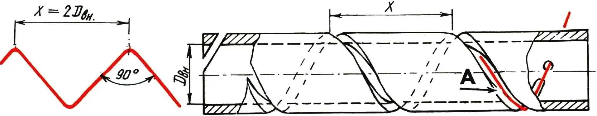
The spiral slot can be made on a lathe in metric thread cutting mode. In this case, the pitch of the slot should be twice the DBH of the cylinder (or the knife width), because the smaller the pitch, the greater the effort required for winding. The slot width should be at least two wire diameters, and the number of turns on the cylinder should not exceed three or four.
With manual winding, up to six linear meters of solid mesh can be made per day.
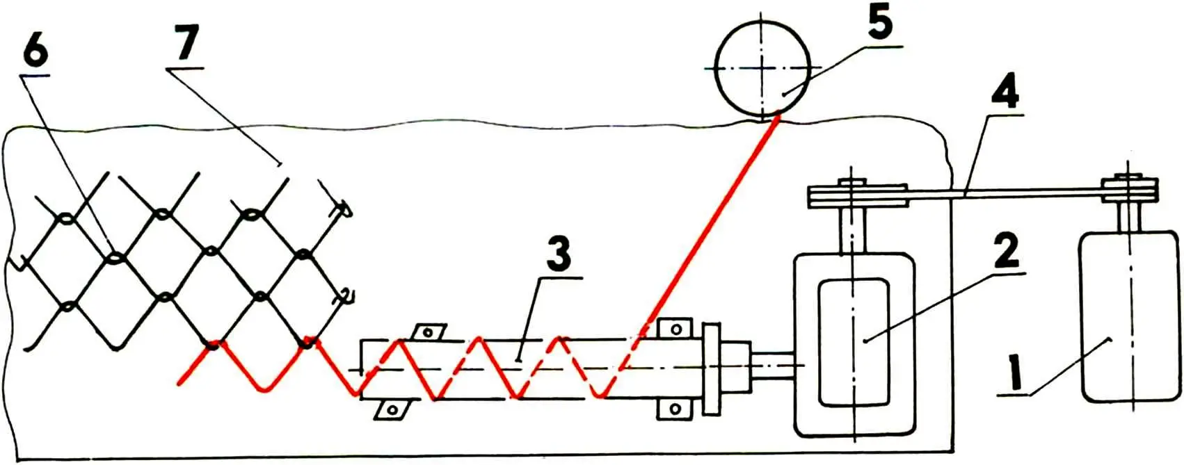
1 — electric motor; 2 — gearbox; 3 — winding mechanism; 4 — belt drive; 5 — wire coil; 6 — mesh; 7 — table.
A mechanized winding method is also possible, when the knife is driven by an electric motor. For this, a 1.5 kW motor will do, for example, a three-phase motor at 1500 rpm connected to a standard single-phase network according to the scheme repeatedly described in the magazine. The optimal knife rotation speed (40–60 rpm) is provided by a worm gearbox with a gear ratio of 15, connected to the electric motor through pulleys by a belt drive. This option is convenient when using a wire coil, which is fed continuously along the full width of the mesh and automatically woven in the winding process; all that remains is to stop the motor in time with a foot pedal, cut and bend the end of the strip, and feed it again to get the next one.
G. KARPACH
Recommend to read
 MAIN BATTLE TANK Leopard 2
After the termination of cooperation with the United States of works on creation of a promising tank MBT-70 in Germany, decided to design a tank of the 3rd generation of their own. By... HANDLE FOR BOTTLES…
Carry a bottle of not very good, but if three of them at once, and you carry no bag, no? Make for such cases of plastic plates or plywood that such a compact handle with shaped holes in...
