The drive of the tracks is made using two pairs of rear sprockets connected by promezhutochnykh. Drive and idler sprockets are identical and are made of the PCB 18 mm thick (Z = 12). The intermediate shaft has side sprocket (Z = 45), which is transmitted torque from the engine through chain transmission. Both propeller rotate synchronously; turn motobug is carried out by changing the direction of the entire mototada.
Fig. 3. A glass-tip:
1 — carrying spar (channel 45×30), 2 — the shank of the Cup (the channel 41X25), 3 — the case of the glass, 4 — shaft sprocket, 5 — pressure washer (nut M42), 6 — Ganka М16ХІ.5, 7 — bolt shank М8Х20, 8, 9,11 — spacers, 10 — bearing No. 203.
Now about the power plant. Many fans use of puskach PD-10 with the Izhevsk cylinder. Such combination only with the engine PD-8 and the cylinder from the Tula scooters, failed me. The fact that the PD-8 inlet ports of small cross section, so thanks to the replacement of cylinder on cylinder scooter T-200 or Tulitsa engine power increases from 8 to 10-12 HP As the cylinder head for the PD-8 is designed for large volume of the combustion chamber, so as to keep the same compression ratio as on the T-200, had to use motorolleri head. In addition, Carter’s PD-8 was undercut ledges of the former reducer. The result is a simple and reasonably reliable engine. Starts the motor by means of a cord, which on the left the axle of the crankshaft pulley installed.
Fig. 4. Track:
1 — rail Assembly, 2 — clip, 3 rubber bands, 4 — rivet.
A key element of motorig transmission — CVT, combined with a dry double disc clutch, made my own calculations, but I can’t recommend to repeat it to others in the same execution. The fact that the variable I was hoping for a specific strap that’s available. I think his design and some parameters (in particular, the control range) can be improved. The only thing I can recommend to fans: if the belt is relatively narrow, to increase the regulation range of the drives of the pulleys, it is useful to be milled, that will allow the pulley halves to enter into each other (matolyak is a mutual occurrence is 10-15 mm). In a similar way used the enthusiasts of technical creativity from Khanty-Mansiysk V. Me-ledin, A. Abdurashitov and V. Kurzenko . Also, I will not lead and drawings of mechanism of reverse of motorig, as all five of his gear is homemade and it hardly makes sense to repeat them one by one.
During the operation it was found that a significant portion of power consumed for rotation of the propeller. It is advisable therefore, to reduce the thickness of the track up to 4-5 mm to give it more elasticity. There are reserves and in facilitating the design: many of its power elements can be made from lighter materials. To decrease the specific load on the ground is useful to increase the width of the tracks. So I have plans in the future to significantly improve their “Blizzard”.
N. SKREBNEV, G. K a R p I n s K, Sverdlovskaya.
Recommend to read
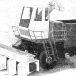 CABBAGE CLEANS THE HARVESTER
The development of specialized agricultural systems is unthinkable without the complete mechanization of manual labor. Many vegetable) crops do not require manual labor for their...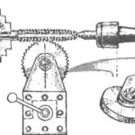 THE WORM GEAR ON A LATHE
We offer to your attention a simple device with which a lathe can cut the worm wheel with any number of teeth. As the cutting tool used here is the standard tap mounted in the Chuck of...
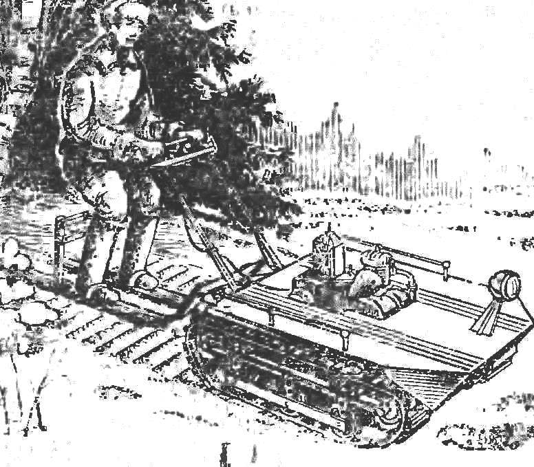
 In a snowmobile “Blizzard”, which I constructed based on many developments, published in “M-K”, merged circuit elements of classic motoart, “amfitriti”, the snow. pneumona and aerolis, that is, almost all the famous trails of mechanisms. However, my vehicle can not be assigned to any of these groups — it’s the combination motorolaring propeller and skis, which is the driver. So I called my snowmobile motoliam. The ka drive them really very similar to the usual walk on the wads, because the driver drives a snowmobile standing up. Experience of its operation showed that the scheme has a number of advantages: high flexibility and good permeability at quite a satisfactory speed — up to 15-25 km h