
 In the manufacture of engine AG-1 used many components from mass-produced engines of domestic production. So, for example, cylinder, cylinder head with studs, a piston finger and piston rings — engine M-106, M — 115, crankshaft, shaft seal and the electronic ignition system with flywheel maggino — VP-150M. Carter taken from the widespread outboard motor “Arrow” (or “ZIF”), Perhaps the use of the cylinder-piston group crankshaft from the engine “IZH-Yupiter”. Additional mechanical treatment of serial parts is as follows.
Carter. Half of it (Fig, 1) inside chiseled stepped up to Ø 103 Ø 93,5 mm along the contour of the placement of the crankshaft. To narrow crank chamber in the halves are mounted in place a new aluminum ring Ø 93/52, thickness 5.9 mm (POS. 4), and bearing housings Ø zapressovyvajutsja rings are 52/40 with a thickness of 5.5 mm (POS. 5) beneath the lip seals (POS. 7). The outer annular ledges chiseled in place to embed one side of the sprocket drive chain 10 mm thick, with another — the Foundation of the flywheel maggino (POS. 11). For the lubrication of bearings are drilled to place the radial holes Ø 4 mm.
The cheeks of the crankshaft (POS. 3) grind the outside diameter from Ø to Ø 94 mm 92 indigenous cervical zapressovyvajutsja steel ring Ø 25/20 3.5 mm thick for a secure fit of ball bearings No. 205. In the connecting rod of the crankshaft (POS. 8) press the new bronze bushing Ø 15/14 and a length of 17 mm (POS. 10) piston pin Ø 14 mm.
In the skirt of the piston opposite the inlet Windows of the cylinder is cut a rectangular window with a width of 28 mm and a height of$ 1 mm, to increase the phase of intake in connection with use of the flap valve. Due to the fact that Carter from the boat motor “Arrow” has a low height for the cylinder is necessary to make an intermediate spacer (Fig. 2), cast alloy or milled from billet. It is secured to the crankcase by four studs M8.
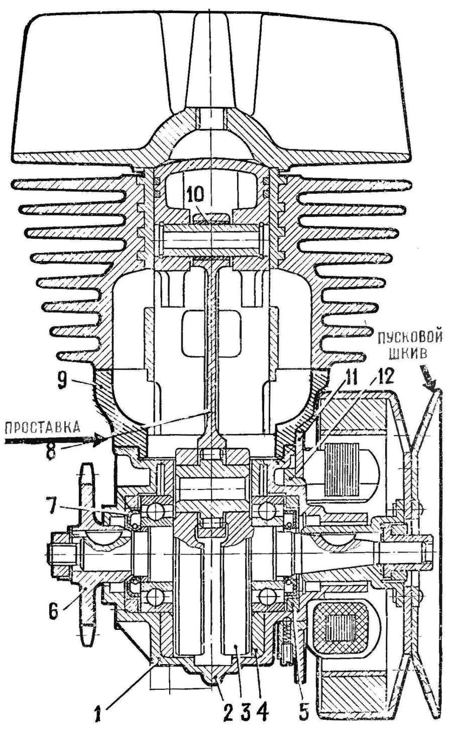
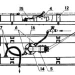
Fig. 1. Engine longitudinal section AG 1:
1 — left half of the crankcase, 2-g – right half of the crankcase, .3 — cheek of the crankshaft, a 4 housing seal o-ring, 5 — ring under the lip seal, 6 — gear sprocket. 7 cuff, 8 — rod, 9 — prostance between the crankcase and the cylinder, 10 is the upper bronze bushing connecting rod 11 — base maggino VP-150, 12 — speed ring.
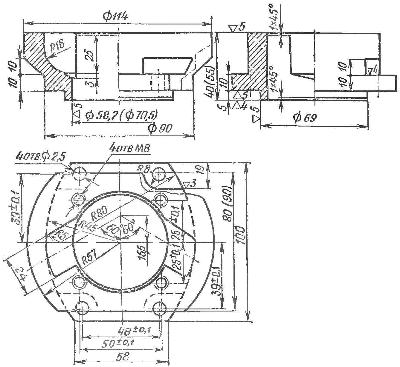
Fig. 2. Spacer between the crankcase (from the boat motor “Arrow”) and the cylinder (motorcycle M-106). The billet is cast from alloy AL-9
Engine Assembly is not difficult, and is performed in the following sequence: first in both halves of the crankcase are pressed one lip seal, and the crankshaft napresovuyut on both sides of the bearings No. 205; on the connecting rod is assembled piston with pin and rings. Then on the crankshaft on both sides wear pre-heated to 80 -90° halves of the crankcase with seal and pull between a radial connector four screws M6, two of which are locking. After that, four M8 studs of the crankcase is mounted intermediate the spacer and the gasket, then the four studs M8 spacer and the piston fits the cylinder head, and all the shrinks nuts M8. The remaining nodes are collected in the usual manner.
Despite the complexity of the electronic ignition system and slightly more weight compared to aggregate magneto, its use is justified (see “M-K”, 1974, No.). Base maggino (Fig. 1, POS. 11) is centered on the stepped ring (POS. 12) bored to Ø 59 mm internal hole and are securely fixed using two ball locks. When adjusting the ignition timing base maggino can be rotated manually or be mechanically connected with the throttle lever of the carburetor, as in outboard motors. For the convenience of the output wires from the bottom of the base maggino socket with a block of diodes and the ends of the conductors perebivaetsya on the right side of the ignition coil and is located adjacent to the inductive sensor. The ignition coil is mounted on the crankcase under the exhaust pipe, and a thyristor unit is fastened on the other side of the crankcase, next to the inductive sensor. The flywheel is mounted launcher maggino aluminum pulley for coiling the cord manually start.
Original engine Assembly is a flap valve (see Fig. 3) installed between the carburetor and the inlet window of the cylinder and consists of the following parts: intermediate pipe-casing (POS. 2) made of aluminum, a pyramidal housing with four plate valves (POS. 3) and transition textolite inserts (POS. 4) between the square opening of the valve and the round hole of the carburetor (POS. 5). All valve parts with gaskets and the carburetor attached to the cylinder on the two studs M8 dural. Drawing flap valve is shown in figure 4.
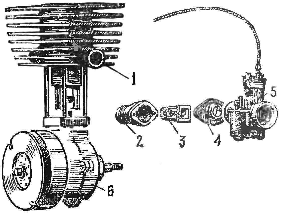
Fig. 3. The scheme of division of the flap the suction valve on the engine AG-1:
1 — suction side of cylinder 2 intermediate pipe (casing), 3 — pyramid case four valve, 4 — transition textolite insert, 5 — carb-TO-36C, 6 — Carter.
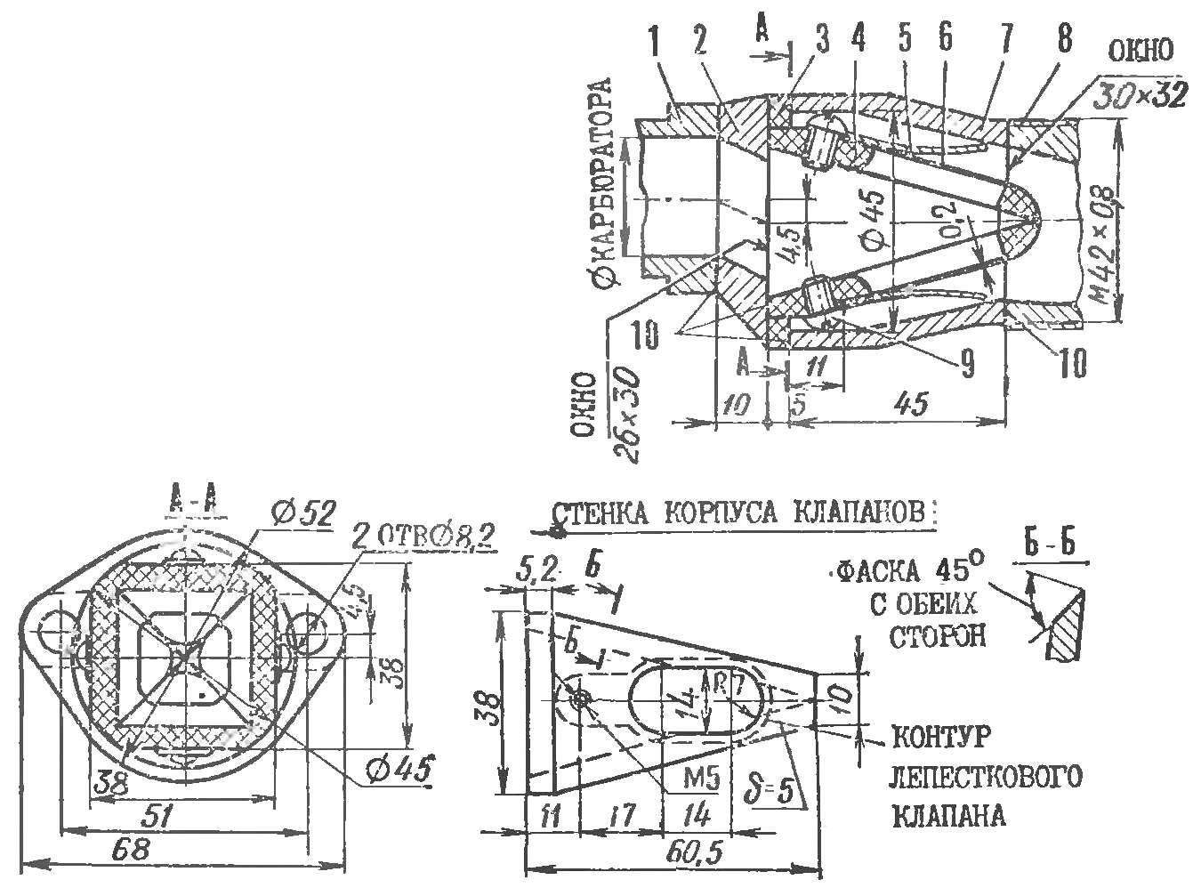
Fig. 4. Block design flap valves:
1 — the carb flange, 2 — transition insert, 3 — flange, 4 — body of the PCB, 5 — deviation limiter valve, 6 — petal valve, 7 — casing, 8 — C suction valve cylinder, 9 — retaining screw M5, 10 — strip.
A quadrangular pyramid-shaped housing (POS. 4) consists of a glued on the epoxy of the flange and the wall — plates of textolite with a thickness of 5 mm, which is pre-drilled oval holes in the valve plate of spring steel with a thickness of 0.2 mm. Plates (POS. 6) and split the limit switches of the valves (POS. 5) is taken from the flat four valve boat engine Veterok and are attached to the four walls of the housing with screws M5 (POS. 9).
Applied design of a pyramidal four-lobed valve is small in size, has a low resistance to the absorption and does not increase the volume of the crank chamber. Installation of the valve on the engine allowed, in addition to receiving an excellent launch and acceleration at moderate speed, to extend the intake phase with a 136° (standard engine of a motorcycle “Minsk”) to 170° that is 25%, which correspondingly increased and the engine capacity is roughly 20% with the same fuel.
The author hopes that a lightweight single cylinder engine AG-1 with a flap valve to drive the propeller for its simplicity, reliability and low specific weight (about 0.8 kg/HP) will appeal to many designers and fans of planes, gliders, microplane, wig vehicles and hovercraft.
Recommend to read
 HOT? ANYTIME!
The proposed boiler is designed for heating cold water (temperature up to 60° C) in apartments with Central or local water supply. Facilities associated with the operation of the boiler,... HOLDING MAGNET
Though served the old speaker, and his ring magnet is still strong. Use it for hanging tools. Hold it firmly on any metal surface, for example, repaired the machine, so that the...
