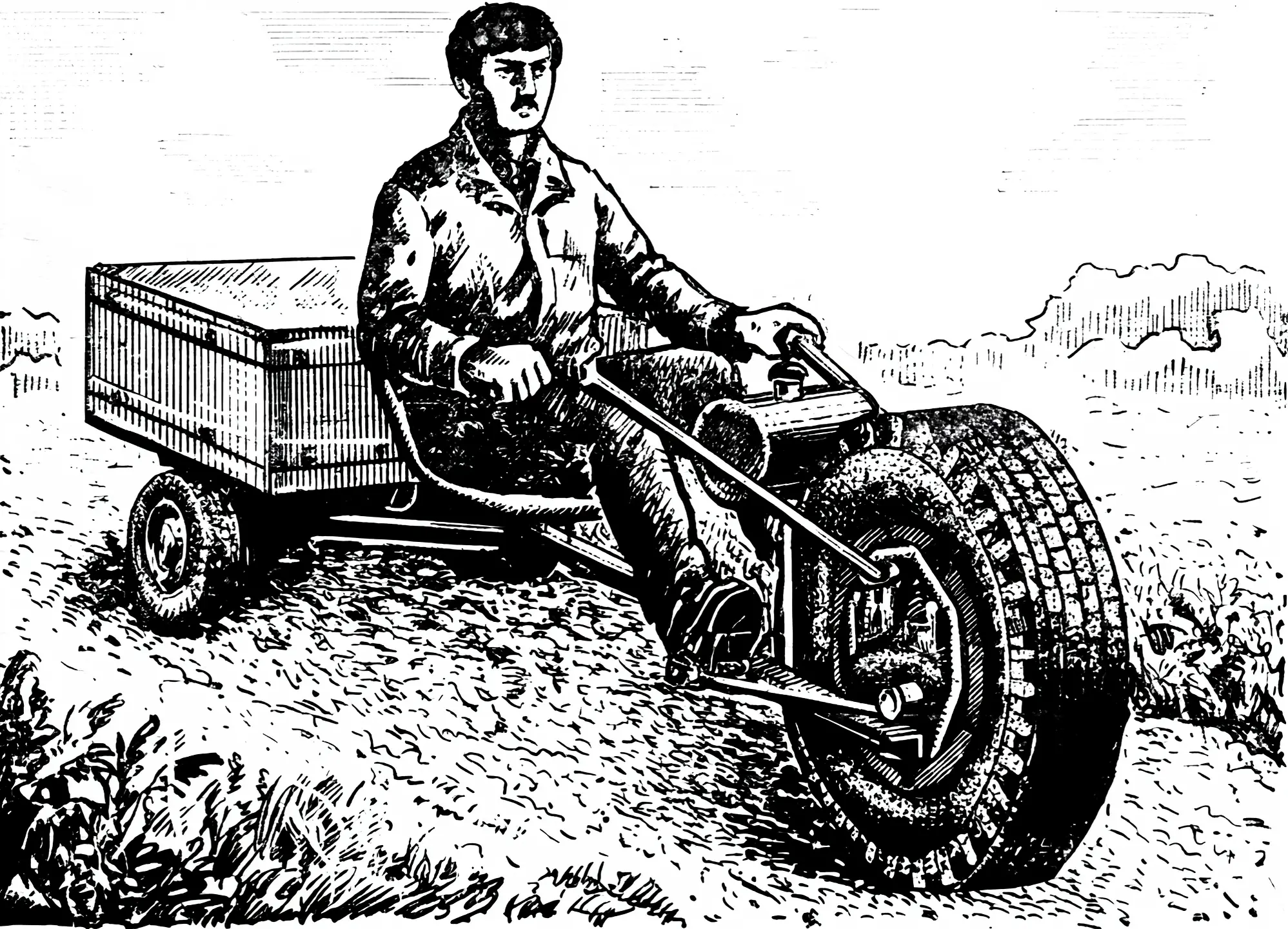
Compactness, maneuverability, and good traction characteristics are the undoubted advantages of the single-wheel tractor built at the young technicians’ station in the city of Novotroitsk. They were achieved by using a layout unusual for walk-behind tractors — “wheel–motor” — which gives the machine minimal dimensions and a simple transmission.
It is no secret that large-diameter wheels have better cross-country ability. When used in a tractor, they also provide good grip with the ground thanks to a larger contact area. However, if the power unit is mounted above the wheel or behind it, the walk-behind tractor becomes either too tall or too long. So why not use the inner volume of the wheel by placing the engine in the center of a ring-shaped disc?
In our tractor we used an engine from a T-200 motor scooter. It is mounted on a welded tubular frame that rests with five guide rollers on the inner rings of the wheel disc. The engine output sprocket is connected by a short chain to an intermediate shaft, on which a drive sprocket for pin engagement with the wheel disc is fixed rigidly.
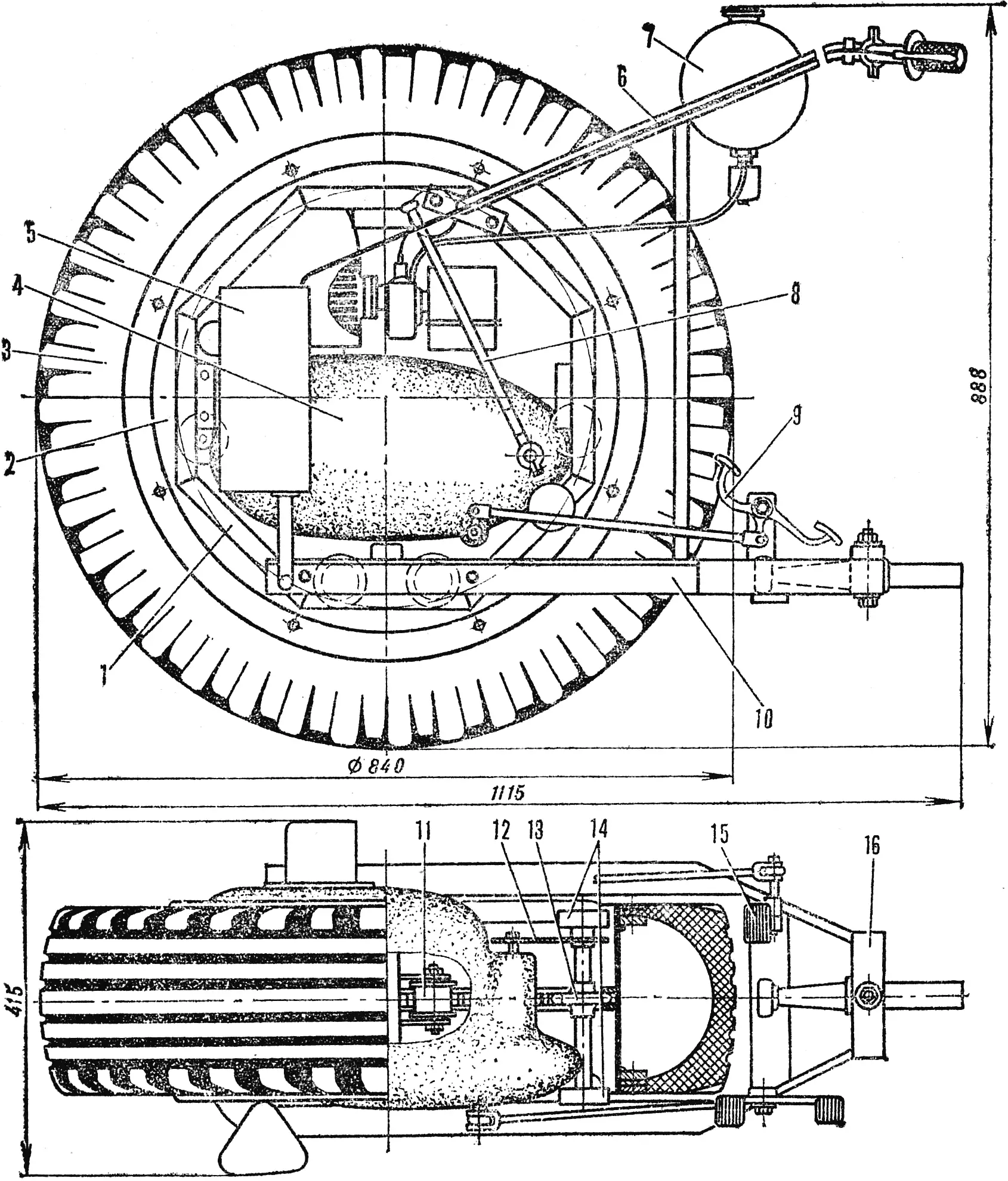
1 — frame, 2 — wheel disc, 3 — tire, 4 — engine, 5 — muffler, 6 — steering fork, 7 — fuel tank, 8 — kickstarter lever, 9 — gearshift pedal, 10 — lower frame fork, 11 — support-and-guide roller, 12 — chain drive to the intermediate shaft, 13 — drive sprocket of the intermediate shaft, 14 — intermediate shaft bearing supports, 15 — brake pedal, 16 — articulated hitch.
The frame that carries the engine, the brackets of the support-and-guide rollers, and the intermediate shaft consists of two octagonal rings welded from identical lengths of 3/4″ water pipe. Both rings are connected parallel to each other by four cross tubular spacers and bolts. This makes assembly and disassembly of the machine easier, because the frame’s support-and-guide rollers are steel rollers fitted with two flanges that embrace the ring-shaped “rail” of the wheel disc.
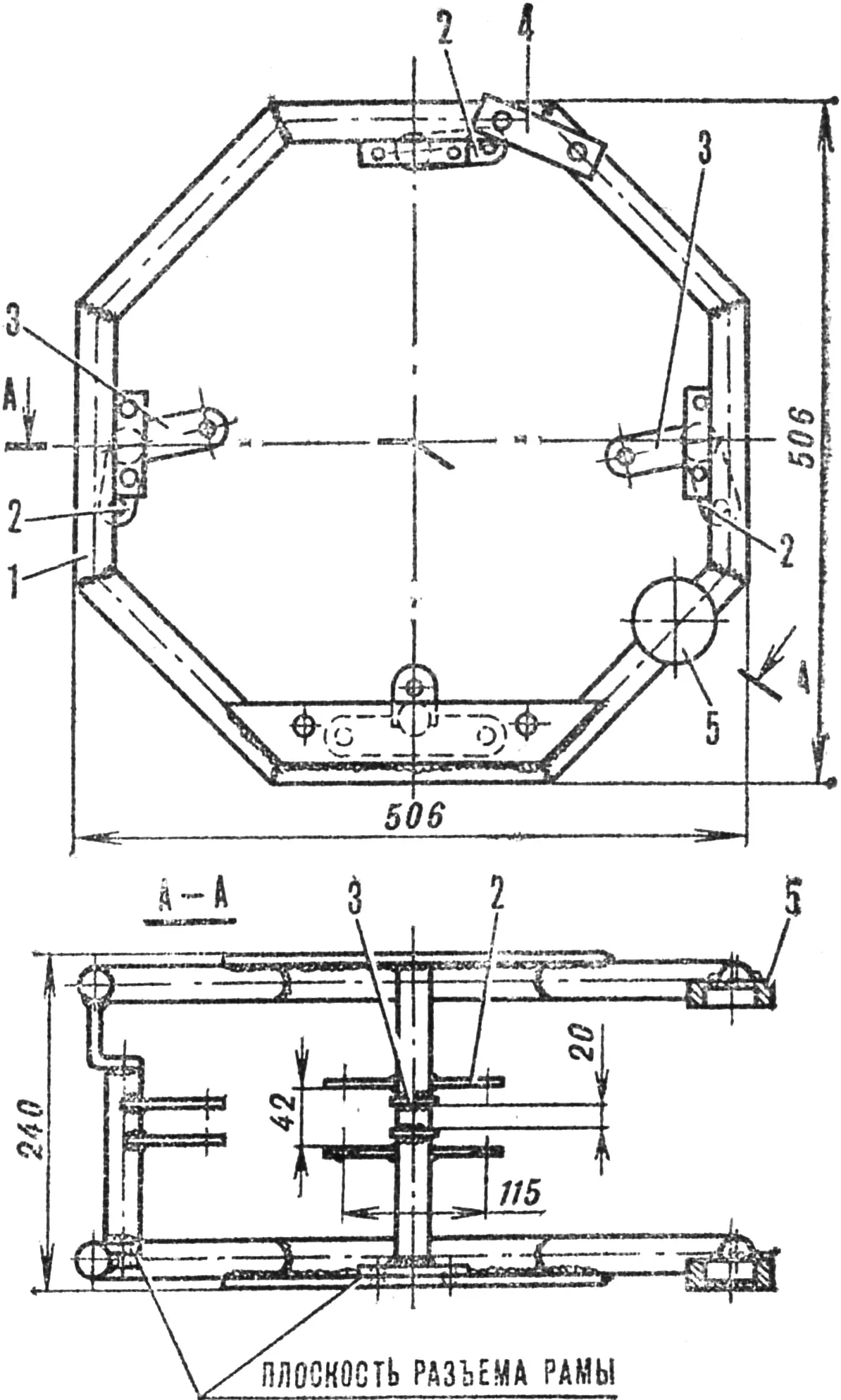
1 — 3/4″ pipe, 2 — brackets of the support-and-guide rollers, 3 — engine mounting brackets, 4 — steering-fork mounting plate, 5 — intermediate shaft bearing housing.
A pair of 40×40 mm angles attached to the lower part of the frame forms, behind the wheel, a support for the articulated hitch and carries the brackets of the gearshift and brake pedals. At the top, a tubular steering fork is attached to the frame. The fuel tank and the clutch and throttle grips are mounted on it. Additional rigidity is provided by vertical posts that connect the upper and lower members.
The wheel disc forms a cylindrical rim welded from a steel strip 1.5 mm thick. On the outer side, 20 mm from each end face, eight steel lugs with an M8 threaded hole are welded. Inside the disc, in the middle of its width, a pin wheel is installed; it consists of two steel rings connected parallel to each other at a distance of 14 mm by a row of cylindrical pins turned from a Ø 14 mm steel rod and hardened. The inner cylindrical surfaces of the wheel rings serve as the bearing surface for the rollers of the engine-carrying frame, while the pins provide pin engagement with the drive sprocket of the intermediate shaft.
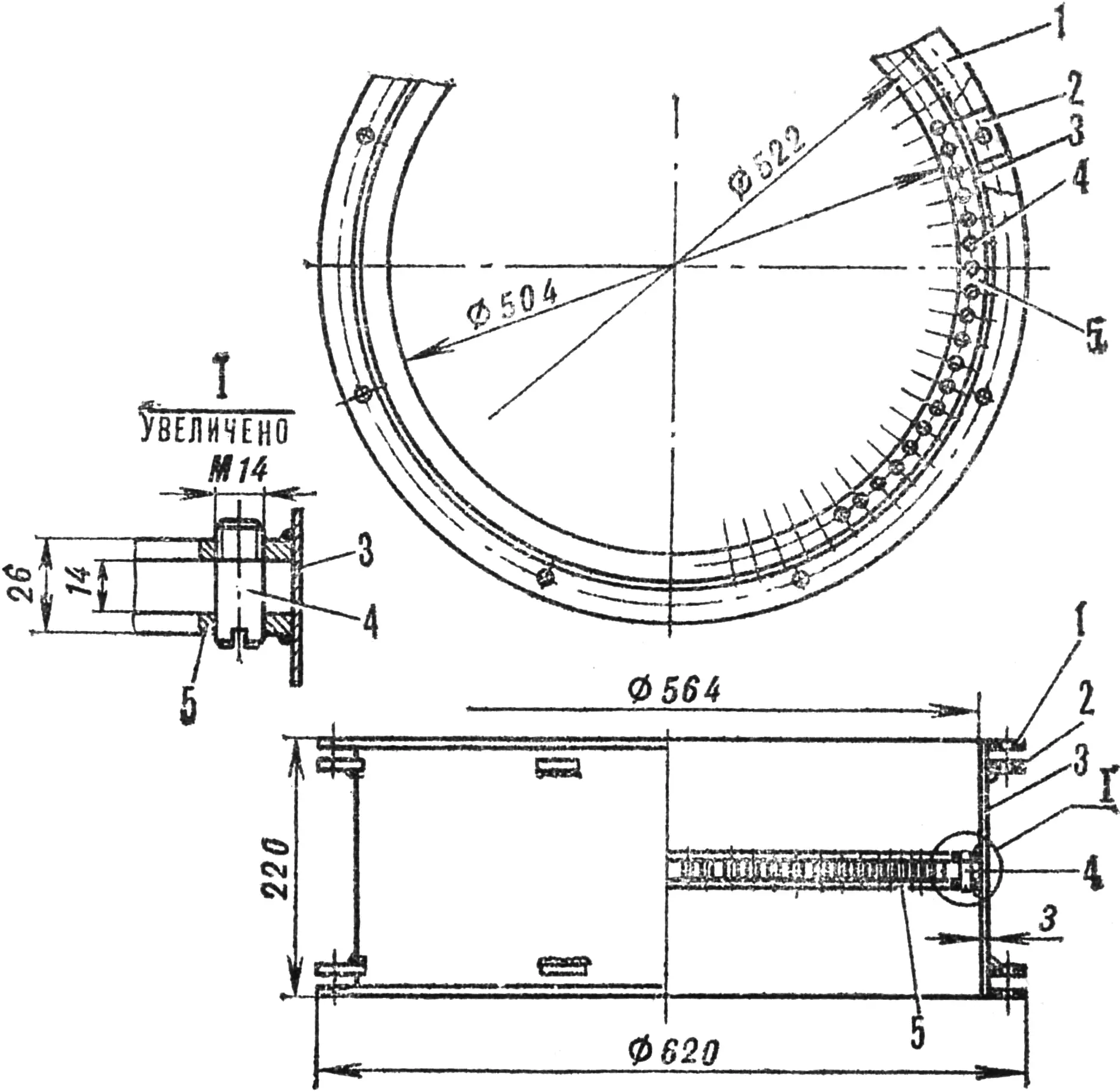
1 — clamping ring, 2 — lug, 3 — wheel disc, 4 — Ø 14 mm pin, 5 — pin ring.
As a tire, the outer part of a tubeless car tire cut to the disc diameter was used. It is better to use a bias-ply tire, because its stiff sidewalls will support the weight of the machine and no air inflation will be needed. Otherwise, when assembling, pack the inner cavity of the tire tightly with rags, rubber scrap, or simply straw. On the disc, the tire is secured by two steel rings that clamp the edges of the beads with bolts through through-holes to the lugs.
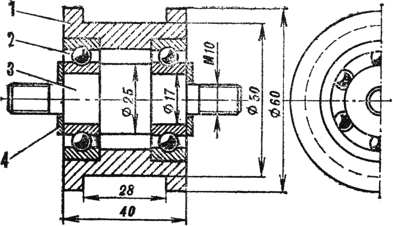
1 — roller, 2 — bearing No. 203, 3 — axle, 4 — washer.
The tractor is intended for use with a two-wheel trailer. Stability in this case is provided by the articulated hitch on the lower part of the frame. It has a vertical axis and a horizontal support pad. The trailer drawbar is fitted with a bushing for the vertical axis and, at the end, with a roller. This design reduces bending loads on the pivot axis.
A set of additional equipment makes it possible to use the tractor not only for transport but also for plowing, cultivation, harrowing, and other soil-working operations.
“M-K” 12’84, A. MASTRYUKOV
Recommend to read
 GOING FROM THE AIR
Photo these aeroamphibious — archive edition. They, along with some technical characteristics of the machines, sent some time ago, Vladimir Pichugin from Kizel, Perm region. The... FROST IS NOT TERRIBLE
No-no and remind myself of the harsh winter the people of our Midland... And when the temperature falls below the normal are given to take additional measures to insulate the apartment....
