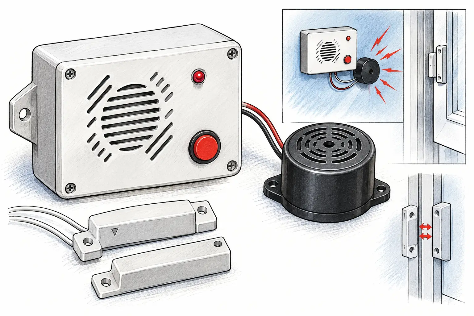
This security alarm device (SAD) is intended for automatic sounding of an alarm signal (electric bell) in case of unauthorized entry of outsiders into a protected premises — an apartment, a country house, or a garage. It features higher noise immunity and the absence of false alarms. The device is powered by a 12-volt battery GB1 made of eight galvanic cells and consumes no more than 5 mA in standby mode.
The SAD includes three comparators. The first is built around logic gate DD1.1 with capacitor C1, resistor R1, and diode VD1; the second — around DD1.2 with capacitor C2, resistor R3, and diode VD3; and the third — around DD1.3 with capacitor C3, resistor R4, and diode VD4. Other parts of the device are: inverters (DD1.4 and DD2.1), an RS flip-flop on elements DD2.2 and DD2.3, an indication unit for power-on and transition to standby mode (DD2.4 with resistor R5 and LED HL1), and a transistor current amplifier (VT1 and VT2 loaded by electromagnetic relay K1, whose contacts K1.1 switch on bell HA1 that sounds the alarm if unauthorized entry into the protected premises is attempted).
When preparing the device for operation (before leaving the premises), the contacts of door sensors SF1 — SFN of the security loop are closed. Then switch SA1 is turned on, applying supply voltage to the circuit. At this moment, logic 0 (logical “zero”) appears at the input of element DD2.1, and at the output, accordingly, logic 1 (logical “one”). The latter is also applied to input 5 of DD2.2.
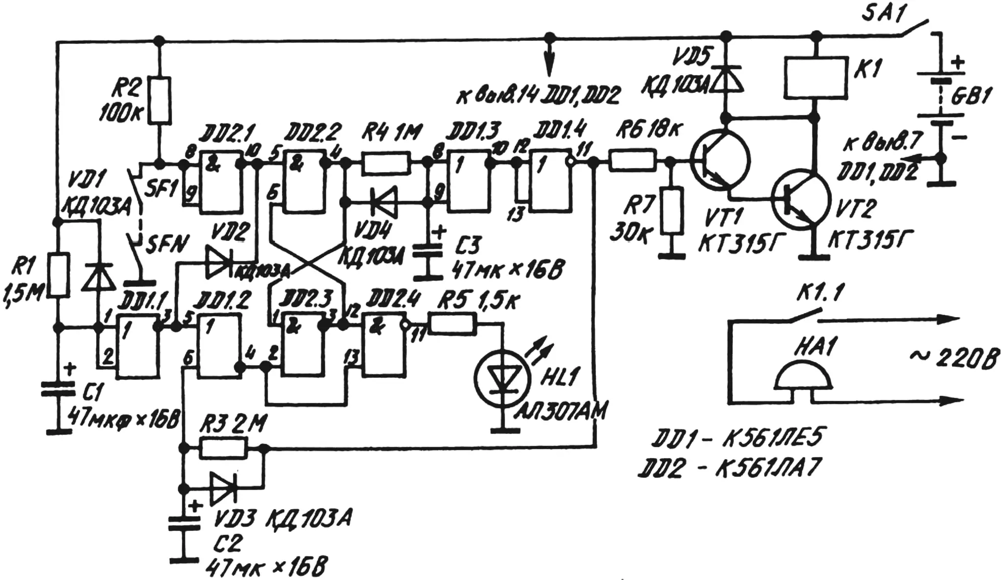
Through resistor R1, capacitor C1 is charged for 50—70 s. During this time, logic 1 is present at the output of element DD1.1, and a low-level voltage is present at pin 4 of DD1.2; this voltage is applied to input 2 of element DD2.3. Thus, the RS flip-flop is in the zero state, characterized by logic 0 at pin 4 of IC DD2 and a high-level voltage at pin 3. This voltage acts on input 12 of DD2.4. But a low-level voltage is present at input 13 of the same logic gate, as a result of which logic 1 is set at pin 11 of DD2.4, lighting LED HL1, which indicates that the device is switched on.
While a low-level voltage is present at input 2 of logic gate DD2.3, a brief opening of sensors SF1—SFN does not change the flip-flop state. During this so-called setup time, one can leave the premises freely.
When capacitor C1 has charged, logic 1 at pin 3 of DD1 changes to logic 0, and a high-level voltage is established at pin 4 of this IC and is applied to input 2 of logic gate DD2.3. The state of the RS flip-flop remains unchanged for now.
At the same time, a high-level voltage from the output of element DD1.2 is applied to input 13 of DD2.4, as a result of which logic 0 appears at pin 11 of IC DD2 instead of logic 1. LED HL1 goes out, which means that the SAD has entered standby mode.
Now any attempt at unauthorized entry into the premises will cause one of the sensors SF1—SFN of the security loop to trip (break their contacts). As a consequence, a high-level voltage will be applied through resistor R2 to the input of logic gate DD2.1. Then logic 0 will appear at pin 10 of IC DD2 and, via input 5 of logic gate DD2.2, will reverse the state of the RS flip-flop. At this moment a high-level voltage will appear at pin 4 of DD2. It is this voltage that will charge capacitor C3 for 30–50 s.
While C3 is charging, a high-level voltage is present at the output of comparator DD1.3, and logic 0 is present at the output of inverter DD1.4. But then the state of this unit changes. The capacitor charges, and the high-level voltage acting on the input of comparator DD1.3 causes logic 0 to appear at pin 10 of IC DD1.
At this moment logic 0 appears at the output of inverter DD1.4 and, through resistor R6, is applied to the base of semiconductor triode VT1, which, when turned on, also turns on transistor VT2. As a result, electromagnetic relay K1 operates and, with its contacts K1.1, switches on bell HA1.
It is also possible to prevent the alarm from sounding (for example, when checking the protected premises or when the owner enters it). For this purpose, the SAD can be switched off with toggle SA1 while capacitor C3 is charging, which, as noted above, takes 30—50 s.
If the contacts of sensors SF1—SFN of the security loop are closed again and toggle SA1 remains in the on position, the high-level voltage present at the output of element DD1.4 will charge capacitor C2. After about 70—90 s, logic 1 will appear at input 6 of DD1.2, and a low-level voltage will appear at the output. It will switch the flip-flop to the zero state, in which logic 0 is present at output 4 of element DD2.2. Then the SAD will again enter standby mode protecting the premises.
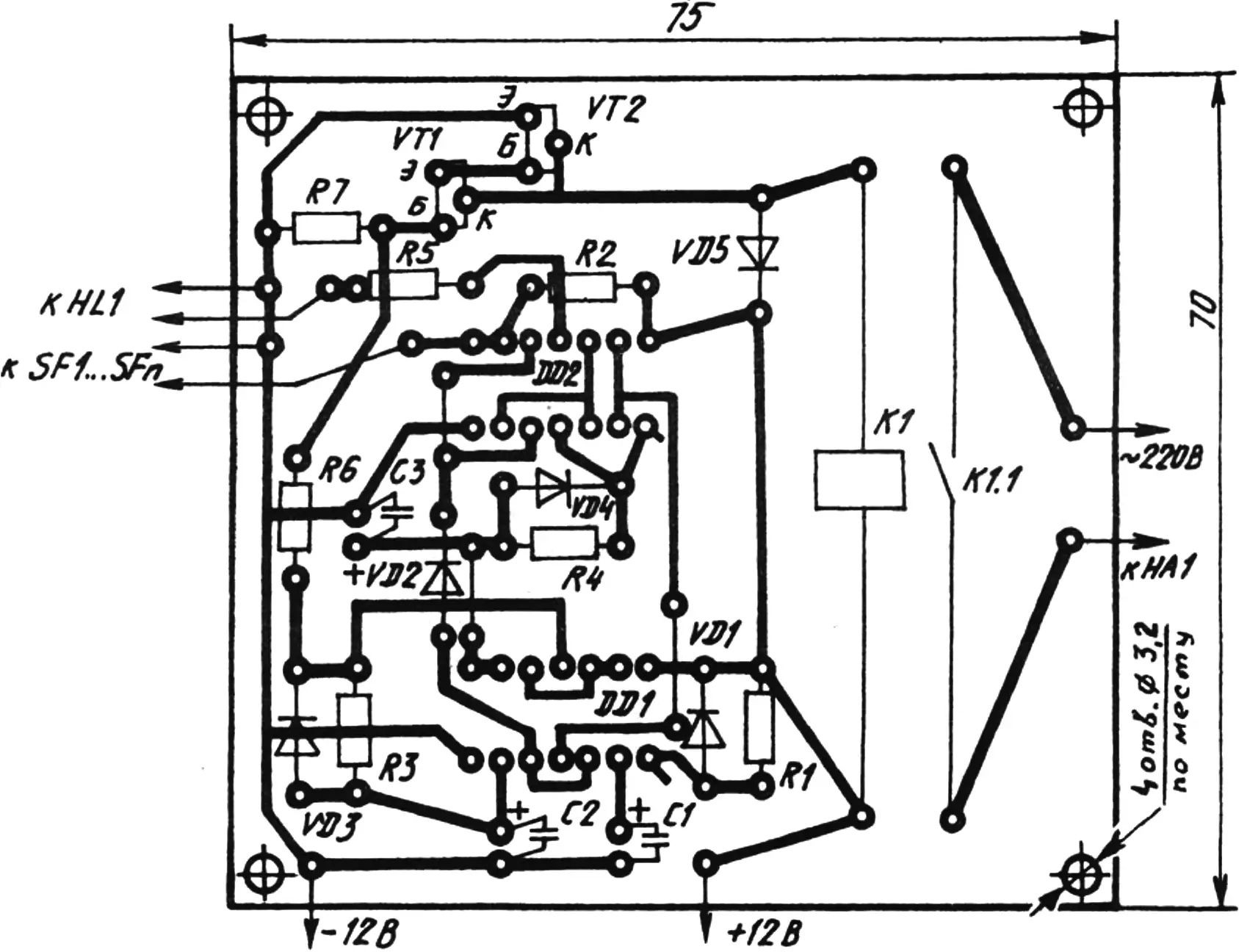
The “internals” of the security alarm device are mounted on a printed circuit board made of 1.5-mm foil-clad getinax. It is recommended to use fixed resistors MLT-0.125 and capacitors K50-35, ICs K561LE5 (DD1) and K561LA7 (DD2), semiconductor diodes KD103A, transistors KT315G, LED AL307AM, relay RPG-5-2101-UZ-12V, toggle switch MT-1, and galvanic cells R20. Typical SMK-1 sensors are suitable for door sensors of the security loop, and DIMK sensors for window ones. A loud-action bell MZ-2 (220 V, 50 Hz) is suitable as an alarm sounder.
Substitutions are also possible. Instead of KT315G transistors, their analogs with any letter suffix in the designation are acceptable. The same applies to diodes and the LED. RPG-5-2101-UZ-12V can be replaced with an electromagnetic relay with a 10 V pull-in voltage whose contacts are rated for a current of at least 0.1 A at 220 V. An electromagnetic buzzer RV4-2 (220 V, 50 Hz) can perform the functions of the bell.
If the assembly is done correctly and from serviceable parts, no adjustment work is needed. If desired, the SAD timing characteristics can be changed by selecting appropriate timing resistors or capacitors in the RC networks.
“Modelist-Konstruktor” No. 7’2001, G. SKOBELEV
Recommend to read
 SHOVEL-DUMPER
It would seem that so simple a tool is the shovel, that to change it or to improve its design is hardly possible. Yes, the handle of the bayonet - that's the device. However, there are... MY HOME IS MY CASTLE
To protect your home from professional thieves and robbers — the task is technically complex and expensive. And the solution to this problem should be dealt with by professionals....
