
For a successful fishing trip it would be nice if good tackle were joined by luck, and also, as they say, “you have to know the places.” And while luck is an unreliable thing, I did know the places where fish could be found. Getting to them, however, was often difficult even for someone on horseback, and even on foot, and there was only one way — by water. But for that I needed at least some kind of boat. So I decided to build a simple fishing boat.
Before starting construction of the boat (or rather, before designing it), I formulated the main desired requirements for it: 1 — stability; 2 — unsinkability; 3 — structural rigidity; 4 — economical performance under an outboard motor; 5 — low weight; 6 — transportability; 7 — sufficient displacement (carrying capacity); 8 — maneuverability; 9 — durability.
There were quite a few requirements, and some of them, moreover, contradicted one another, which forced me to look for a compromise between them. Partly for that reason the boat was made of different materials: metal (duralumin) and wood. I sacrificed maneuverability to some extent for the sake of stability, and capacity (displacement) for small dimensions in the interest of transportability.
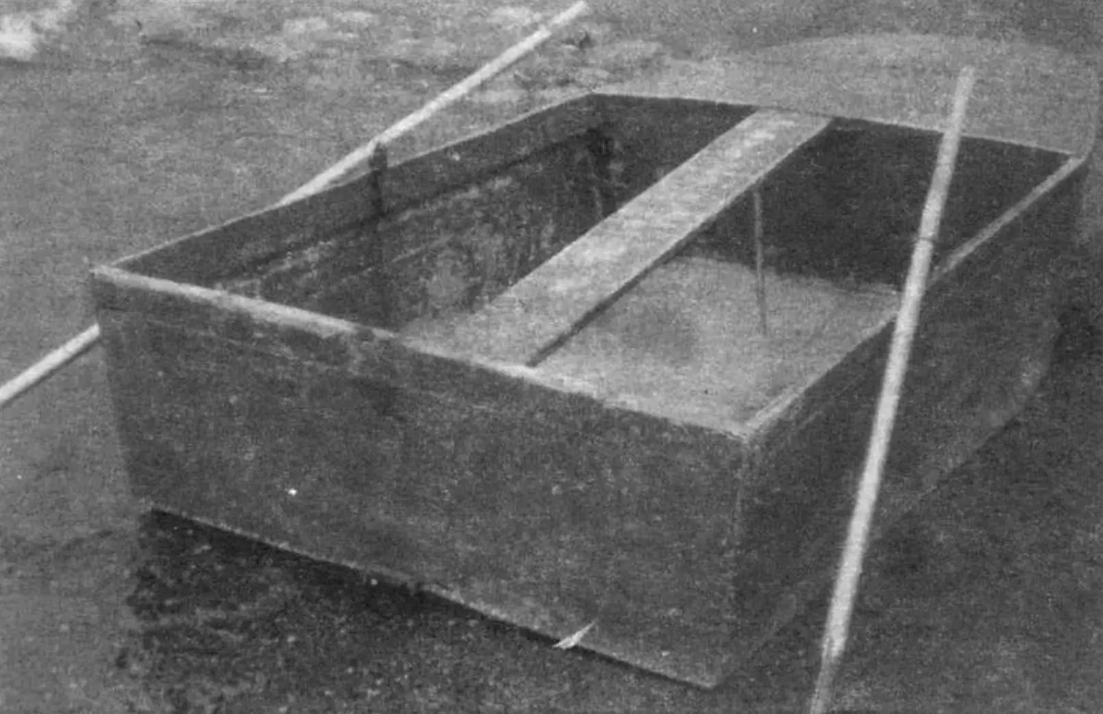
As is well known, a boat can travel through water in a displacement mode (as, for example, self-propelled barges do) or plane (as high-speed craft do). At low speeds, travel in the first mode is economical. But at relatively high speeds such a mode is acceptable only with a sufficiently large length-to-beam ratio of the vessel (1/10 and higher), while for small boats the planing mode is economical. True, for this it is necessary that for every 25 kg of the boat’s weight with everything carried in it there be at least 1 hp of outboard motor power. But by all estimates I reached that figure easily.
Proceeding from this, I began designing the boat as well. The most rational approach was to give its bottom a shape thanks to which the hull would lift itself out of the water as speed increased, i.e., so that the boat could easily get onto plane. Such a shape is well known — a stepped (redan) bottom. But making a step in the bottom in a home workshop is rather complicated work, and moving about on a stepped bottom is not very convenient either. So I settled on a simpler flat-bottomed “ski” version (with a raised bow) — after all, this little craft was not meant for racing.
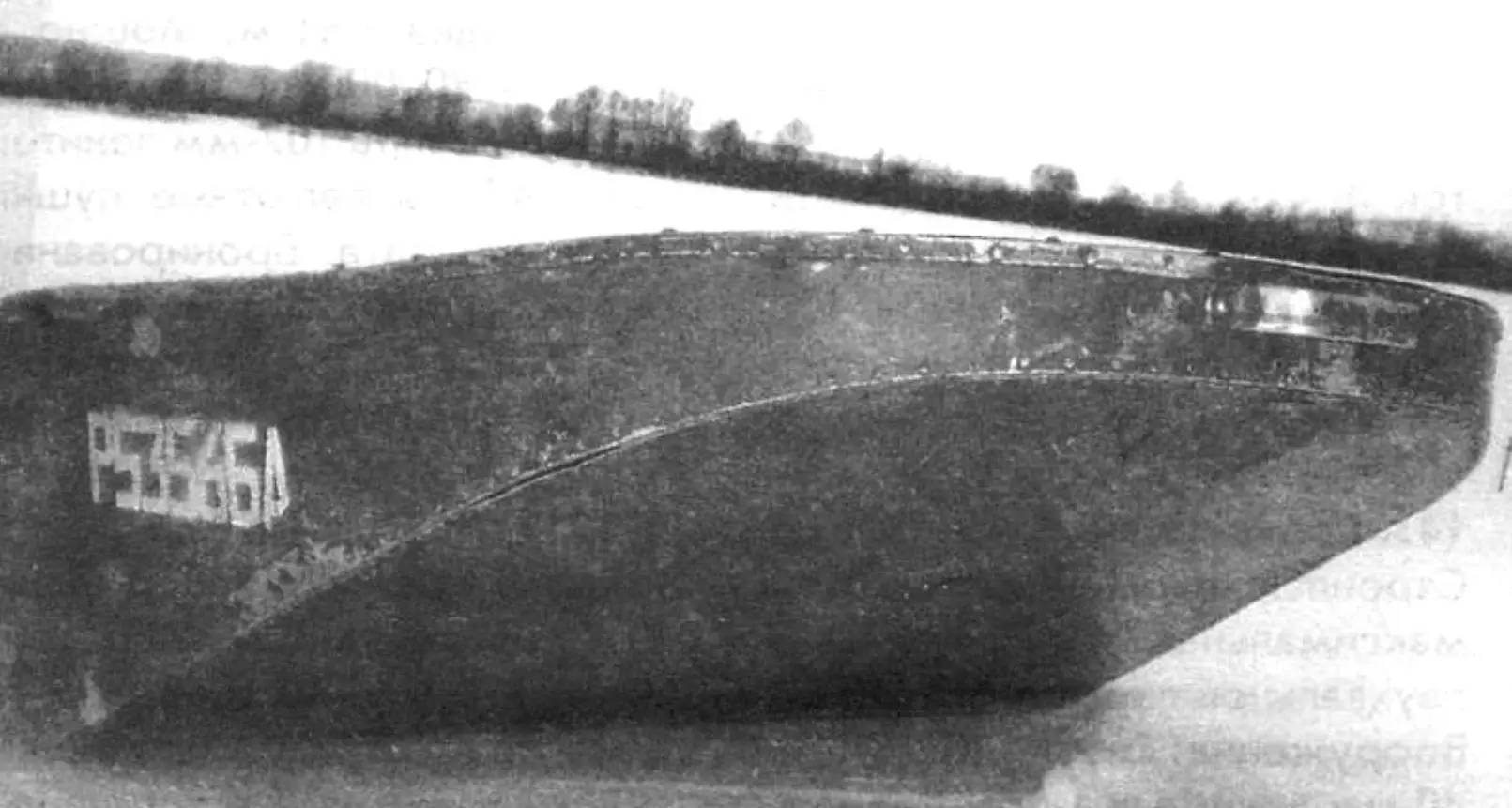
As a result, a simple but strong boat was built for intensive use with a multi-year service life, practically requiring no maintenance and no special storage conditions.
Structurally the boat consists of two parts: a closed forward end — the forepeak — and the remaining open part — the cockpit.
The boat’s hull is made mainly of duralumin sheets. For the bottom a sheet 1.6 mm thick was used, and for the sides, transom, bulkhead and forward part of the bottom — 1 mm thick. All the listed parts are one-piece cutouts (each cut from a single sheet), although nothing prevents riveting both the bottom and the sides from composite panels, making the joint at the place where the bulkhead is fastened to them (only do not forget to add 20-mm allowances on both mating blanks). At the same time, a bottom thickness of 1.6 mm is needed only in the cockpit, while in the forepeak a one-millimeter sheet can also be used.
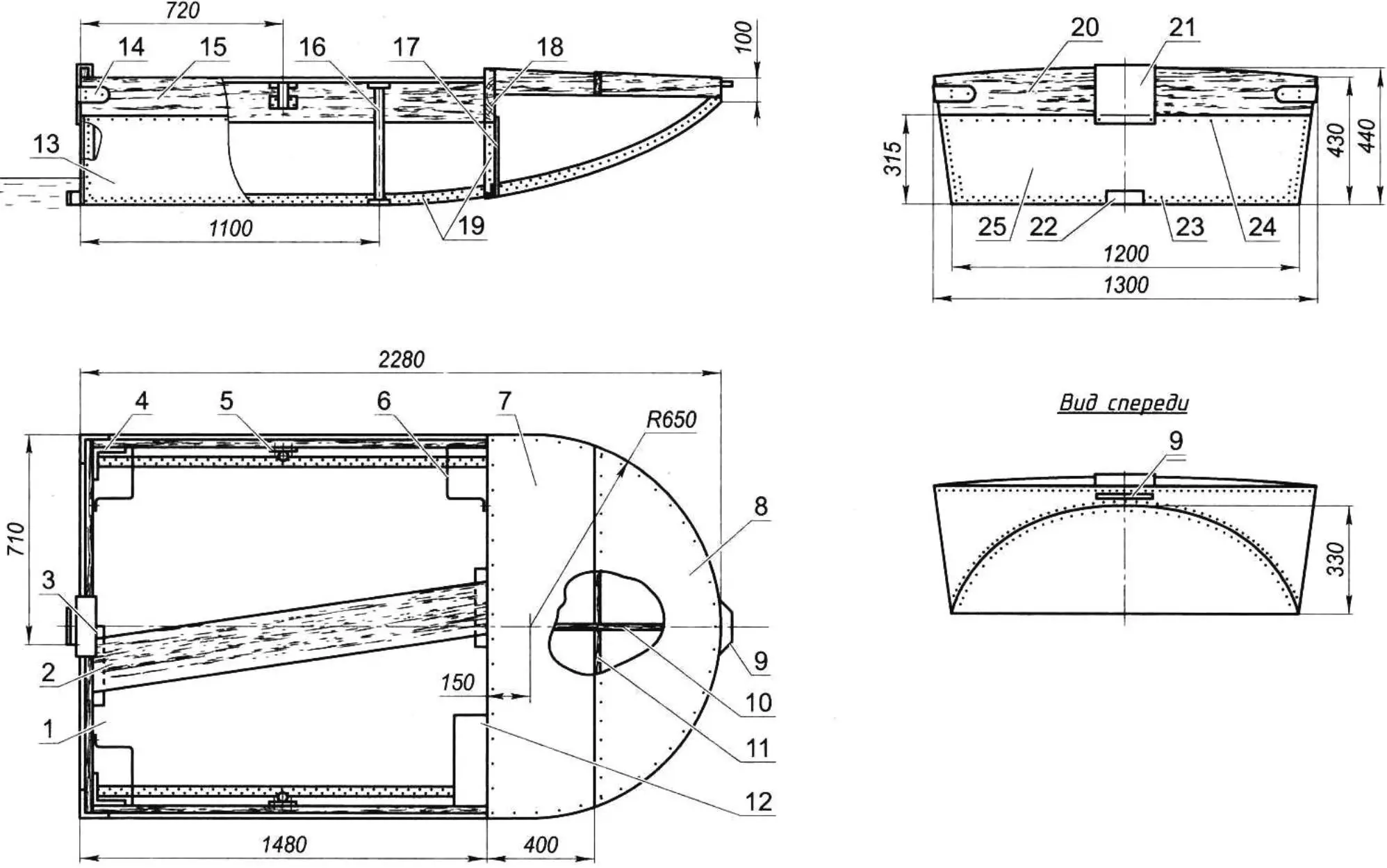
1 — bottom (duralumin sheet s1.6); 2 — seat/thwart (fir board 160×20); 3 — bracket for mounting the seat/thwart (duralumin angle 30x30x2.5, 2 pcs.); 4 — inner corner plate (duralumin, sheet s3, 4 pcs.); 5 — oarlock socket; 6 — clamp for fastening the fuel tank and cans (aluminum strip 20×2, 3 pcs.); 7 — deck plating (duralumin sheet s1); 8 — forepeak cover (duralumin sheet s1); 9 — handle/ring (tube Ø10); 10 — longitudinal under-deck beam — carling (fir board 80×20); 11 — transverse under-deck beam — beam (fir board 80×20); 12 — tackle box; 13 — side (duralumin sheet s1, 2 pcs.); 14 — outer corner plate (s3, 2 pcs.); 15 — gunwale (fir board 125×20, 2 pcs.); 16 — pillar of the seat/thwart; 17 — bulkhead (duralumin sheet s1); 18 — bulkhead board (fir board 140×20); 19 — connecting frame member (duralumin angle 20x20x2); 20 — transom board (fir board 135×20); 21 — motor mounting plate (steel, sheet s2); 22 — damping block (hard rubber 60x30x20); 23 — rivet Ø3; 24 — self-tapping screw; 25 — transom (duralumin sheet s1)
Another 15 linear meters of aluminum angles with flange sizes 20x20x2 mm and about 1000 aircraft rivets 3.5×10 mm in diameter were also required. I do not count fir boards and galvanized self-tapping screws (such, or similar, materials are always at hand for DIY builders).
The use of these materials provided lightness and sufficient strength of the structure. In addition, they (the materials) are relatively easy to cut out and machine. True, joining parts with rivets is a labor-intensive method and requires experience, but I had both the experience and the time. Besides, there are now many good devices on sale that improve the productivity and quality of riveting work.
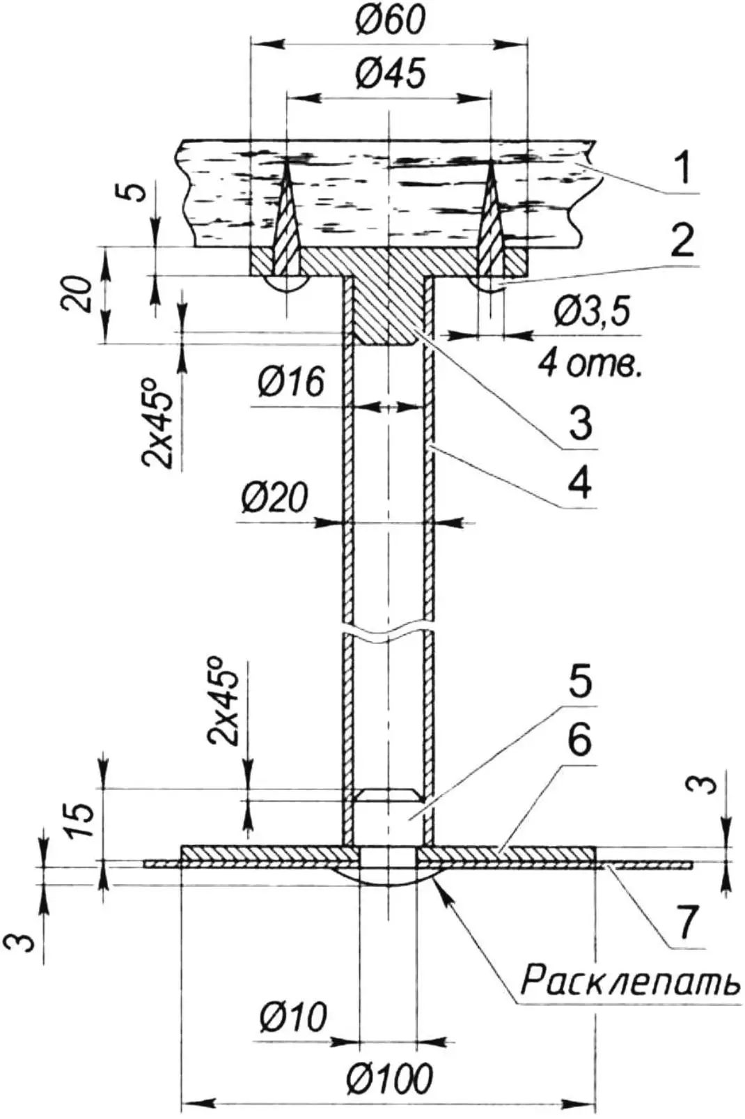
1 — seat; 2 — fastening of the thrust flange (screw, 4 pcs.); 3 — thrust flange (duralumin, round bar 60); 4 — pillar (duralumin tube Ø20); 5 — pin (aluminum rivet Ø10); 6 — thrust washer (duralumin, sheet s3); 7 — boat bottom
The angles are used in the structure as elements by means of which individual parts (panels) are joined to one another and into a single assembly. At the same time they also serve as form-giving (frame) members and even partly as load-bearing ones. But the main loads are carried by the boat’s hull.
The entire cockpit is edged with fir boards (wood of other softwood species can also be used) set on edge. This edging serves both as the cockpit frame (it stiffens the upper free edges of the panels, preventing them from bending) and at the same time increases the freeboard. In addition, the transom board serves as a support for the outboard motor, while the side boards support the oarlocks and also act as pillars and rubbing strakes.
The angles for the boat’s chines (the joint lines of the sides and bottom) are slightly opened to the corresponding obtuse angle and, if necessary, straightened.
Joining of the duralumin sheets to the angles below the waterline is done by installing rivets in two staggered rows with a pitch of 15 mm, and above it — in a single row with a pitch of 20 mm.
A thin layer of mastic is placed in the seam. Care must be taken to ensure that no debris or metal filings get into the joint.
Fastening of the duralumin panels to the wooden structural parts is done with self-tapping screws in a single row with a pitch of 30 mm — these joints are located high enough above the water.
The deck of the boat’s bow end is made in the shape of a semicircle. Bending of the angle to a radius of 650 mm for joining the sides and the deck plating is done toward the previously trimmed horizontal flange down to a width of 12 mm.
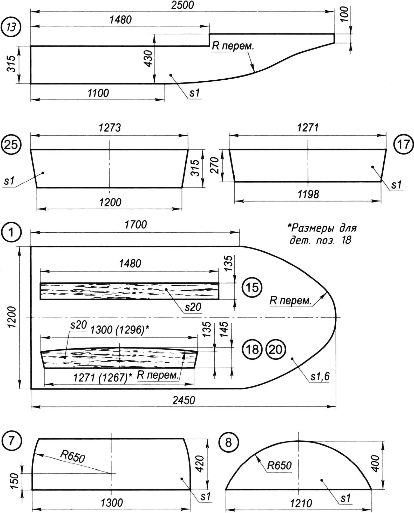
The deck plating over the forepeak is made composite, of two panels cut from 1 mm thick duralumin sheet. Support for the plating from below is provided by two beams: a transverse one (in shipbuilding terminology — a beam) and a longitudinal one (a carling). At the intersection the beams are joined half-lapped. The beam and carling make it possible to step confidently on the deck when mooring bow-on and casting off. For mooring the boat, a handle/ring is mounted at its bow. The first (forward) deck panel is removable; it is the hatch cover for access to the forepeak. It is screwed to the frame angle with self-tapping screws. The second (next) panel is fastened along its side edges with rivets via the same angle to the sides, and to the bulkhead extension board it is also screwed with self-tapping screws. The bulkhead is also made of one-millimeter duralumin sheet. It is fastened to the sides and bottom with rivets through duralumin angles, and the lower angle coincides exactly with the lap joint of the bottom panels and side panels if they are composite. It should also be noted here that the boat has no transverse framing as such, so the bulkhead serves as a frame, as does the transom, for that matter.
The boat’s stern is a transom stern, that is, cut off flat. It is made of a 1 mm thick duralumin sheet and extended at the top with a 20 mm thick fir board 125 mm wide. I will also note here that in order to raise the outboard motor higher above the water, I made the upper edge of the transom board convex. Incidentally, I made the upper edge of the bulkhead extension board similarly convex, but for a different purpose — to give the deck a camber so that water falling on it would run overboard rather than into the cockpit. In the middle of the transom board I fitted a steel plate 1 mm thick so that the motor mounting bracket would not damage the board.
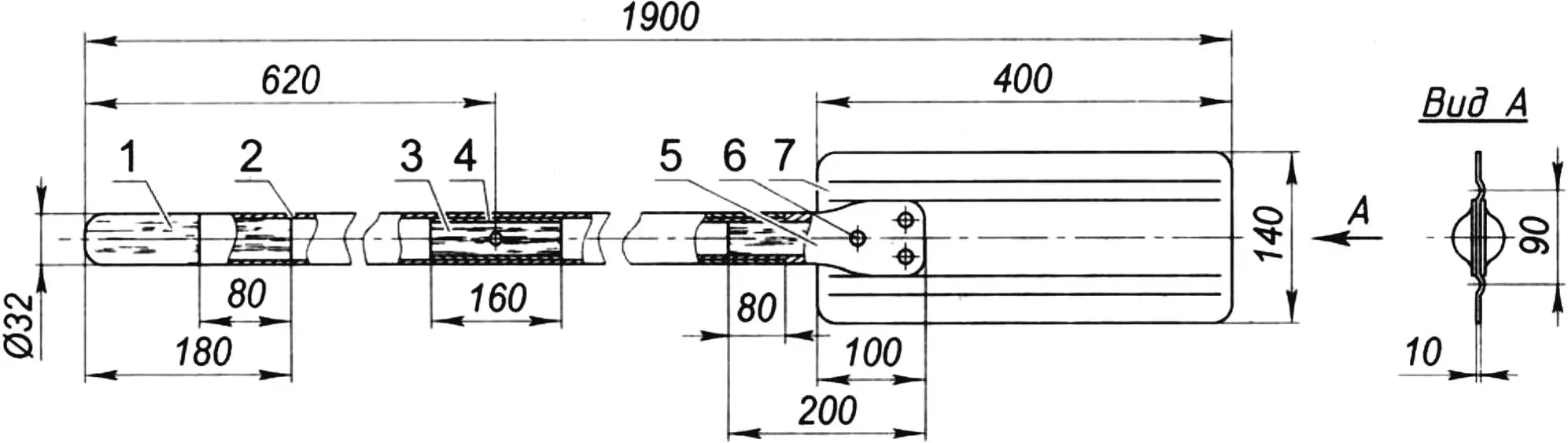
1 — handle (birch); 2 — loom (tube 32×1); 3 — plug (fir); 4 — reinforcement (aluminum tube Ø30×3); 5 — bracket (aluminum tube Ø32×4); 6 — rivet (aluminum, Ø6, 3 pcs.); 7 — blade (duralumin, sheet s2.5)
Although the boat is two-seat, there is only one seat (thwart), and it is mounted not as usual — across the boat — but in the middle along it and slightly at an angle. Such a placement of the thwart is not only much more convenient for fishing, but also allows the helmsman and passenger to take any place in the cockpit depending on the craft’s loading and the state of the water, and also, if necessary, to change places right on the water and even while the boat is under way without the risk of capsizing it or falling overboard oneself. Placement in the boat of a 5 L fuel tank, a box for fishing tackle, and a box for clothes was arranged, as far as possible, so that the bottom remained almost completely free, which improved operating conditions and habitability (if that word can be used for a small-area cockpit open to all winds).
A large, and moreover concentrated, load on the boat’s bottom is transmitted by the seat/thwart pillar installed as a strut. Therefore the lower end of the pillar rests on a washer of fairly large diameter made of 3 mm thick duralumin sheet. The washer is laid on the bottom and riveted to it with a single rivet 10 mm in diameter, and the closing head is made in the form of a pin that serves as a locator for the position of the lower end of the tubular pillar.
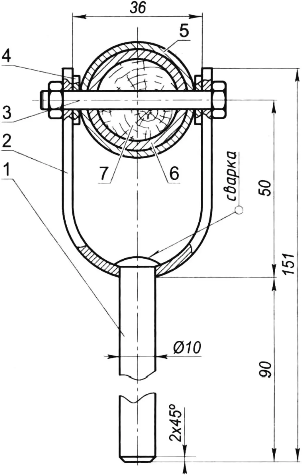
1 — pin (steel 35, round bar Ø10,); 2 — fork (steel 20, strip 20×3,); 3 — oar axle (M6x55 bolt with nut); 4 — gasket (fluoroplastic washer, s2); 5 — oar loom; 6 — reinforcement; 7 — plug
The wooden parts are impregnated with hot drying oil even before assembly. The duralumin parts, just before painting, are cleaned of the oxide film (at the same time roughness is given to their surfaces for better adhesion), degreased and primed. The entire boat, after its parts have been assembled into a single structure, is painted with enamel.
The forepeak is not yet sealed. Therefore the boat’s unsinkability is provided by 20 plastic bottles of 1.5 L capacity each placed in it, and two 10 L cans installed on the bottom in the aft part of the boat’s cockpit and fastened, like the fuel tank, with clamps to the transom.
I tried to make the oars strong, light, convenient and unsinkable. I present their design.
The oar loom is made of a duralumin tube 32 mm in diameter with a one-millimeter wall thickness. At the place where the oarlock is attached, the loom is reinforced from the inside with a section of thick-walled aluminum tube with a wooden plug secured there with epoxy adhesive. The plug is needed to prevent water from entering the oar and so that the oarlock axle-bolt does not wear out the hole in the loom so intensively. Also, to increase wear resistance, fluoroplastic washers are inserted on the axle between the fork horns of the oarlock and the loom tube on both sides.
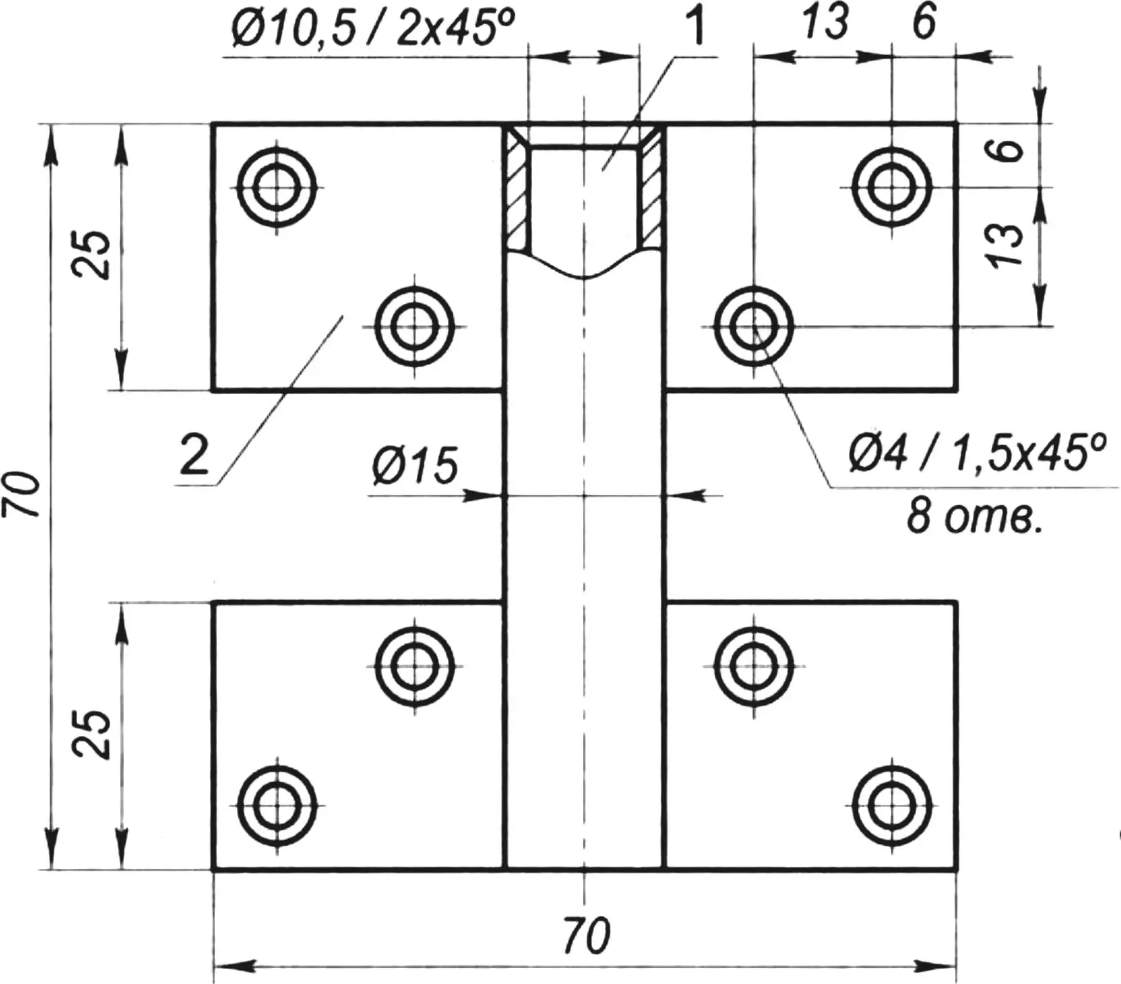
1 — bushing for the pin (steel tube Ø15×2.25); 2 — plate (steel sheet s2, 2 pcs.)
The oar blade is made of medium-hardness sheet aluminum 2.5 mm thick. Along the blade, by bending, two grooves are formed. It is fastened to the loom not directly, but through a transition insert — a reinforcement of the root part of the loom, made of a thick-walled aluminum tube with an outside diameter of 32 mm, also with a wooden plug. So that the reinforcement can be inserted into the loom, one end of the former is turned down to the inside diameter of the latter. At the other end a slot is made for the blade, the end is flattened and the parts are riveted. The reinforcement is seated in the loom with epoxy adhesive. For joint strength, clean fine metal filings or aluminum powder can be added to the adhesive.
It is also possible to make the oar loom from fir. In that case its diameter, and accordingly the distance between the fork horns of the oarlock, should be increased by a factor of 1.5.
The boat’s weight does not even reach 20 kg, while the displacement (total weight of passengers and useful load) was about 130 kg.
The boat is fitted with a modified “Veterok” outboard motor of 8 hp (it has also run under a 12 hp unit). The immersion of the motor’s lower unit is of no small importance. In my case the motor is raised as high as possible, and to prevent air being drawn in, the anti-cavitation plate is widened at the forward part and on the sides — a plate is riveted to it from below. In the planing mode the propeller immersion is about 250 mm, which is quite sufficient — grass and debris floating on the water do not reach the propeller.
I also removed the stop from the “Veterok” outboard motor, and riveted a duralumin angle with a hard-rubber block to the aft side near the boat’s bottom. Such a motor mount not only dampens vibration and shocks better, but also reduces the load on the transom. For the same reason I also removed the raised-position motor fastening, and the engine now stays on its port side in that position even without a stop.
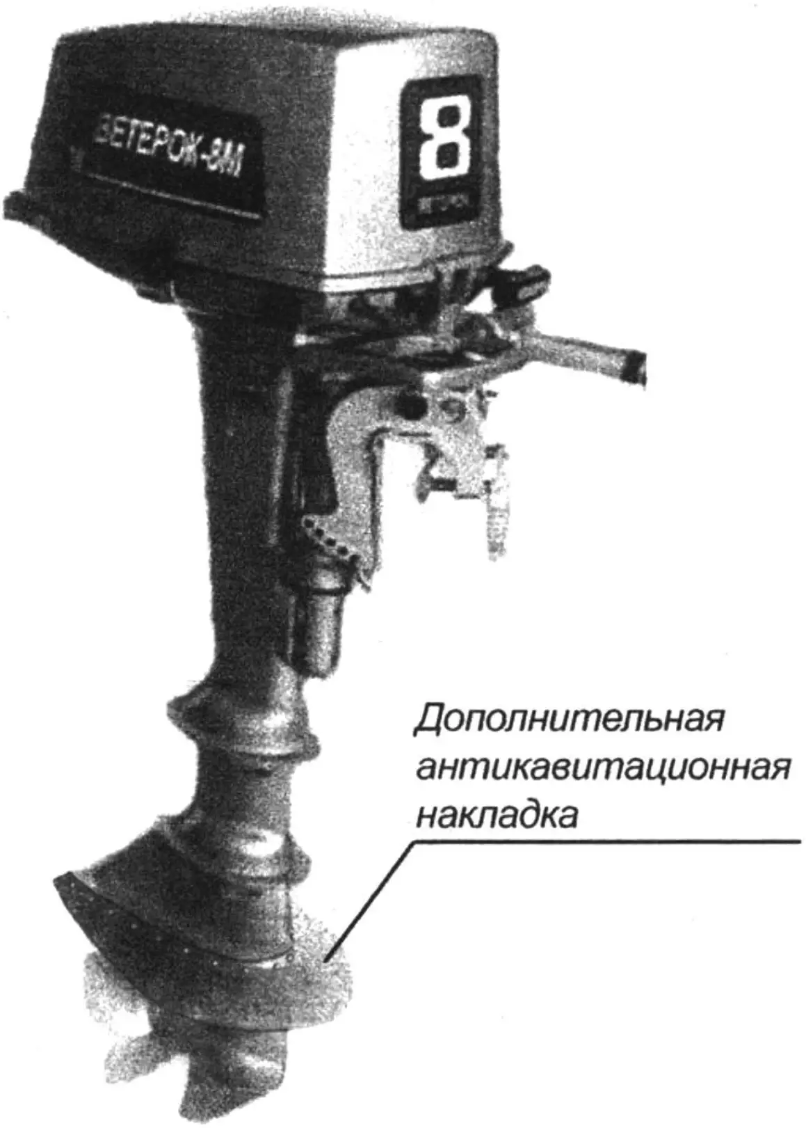
The boat’s speed with an 8 hp “Veterok-8M” motor is up to 30 km/h, and with a 12 hp motor — up to 40 km/h.
With one driver, even under an 8 hp engine the boat easily gets onto plane, and under a 12 hp motor its hull almost completely leaves the water. Further running takes place in an economical planing mode (in terms of fuel consumption) for the motor.
It has been noticed that when there is a ripple on the water, the speed at which the boat gets onto plane increases. Happy sailing to you, or, as sailors say: seven feet under the keel. Only do not forget to put on life jackets, even if you swim well.
“Modelist-Konstruktor” No. 8’2009, R. NIGMATULLIN, Neftekamsk, Bashkortostan
Recommend to read
 JUMP AS HIGH AS POSSIBLE
At first glance, the school gym is the same as thousands of others. But this is only at first glance... Observant person will note here something unusual. On boards and panels, attached... FROM “THUNDERBIRD” TO “SWORD” AND “AXE”
For several decades the Soviet patrol ships (TFR), formally considered as analogues of foreign frigates and corvettes, it was actually the destroyers — shock military units near the sea...
