
The mini-system I developed is designed for automatic maintenance of set air temperature and humidity in thermal cabinets, closed boxes, as well as in greenhouses or other rooms. Its design is mainly modular (Fig. 1); assembly is quite within the capabilities of anyone who has ever put together even a simple electrical or radio circuit — if not by soldering, then at least using connectors and twisted joints.
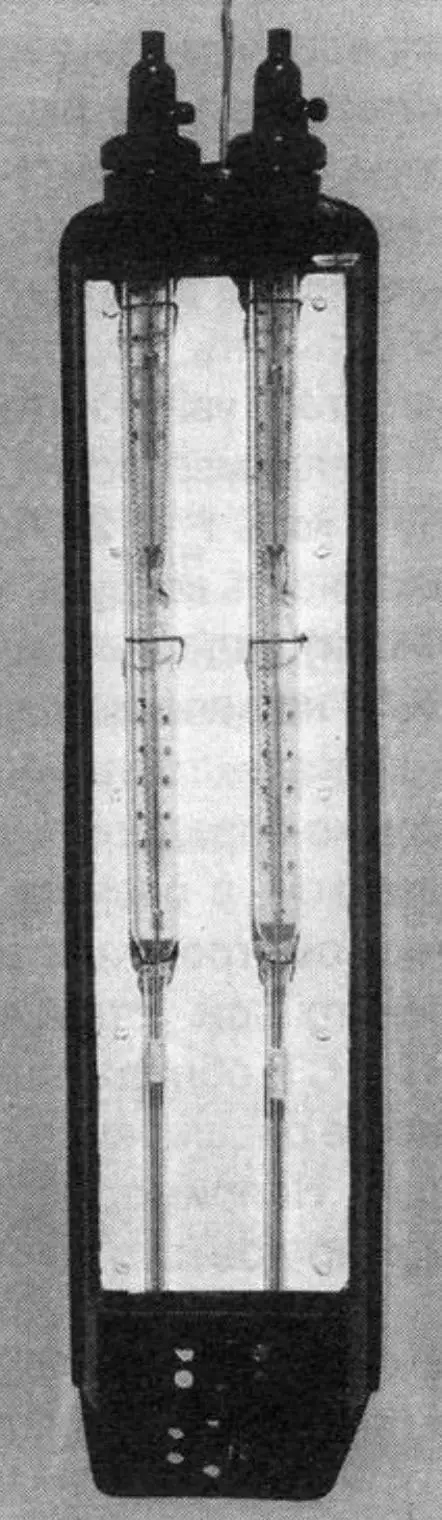
The system’s sensing elements are two glass mercury electrocontact thermometers of the TPK type, familiar to everyone from school physics lessons, mounted on a plastic stand (Fig. 2). A gauze sleeve is pulled over the mercury bulb of one thermometer, hereinafter called WET (abbreviated WT) and used for visual determination, setting, and maintenance of the desired ambient air humidity; the sleeve is lowered into a small vessel with water. The other thermometer is called DRY (for short — DT) according to the condition of the mercury bulb, onto which nothing is pulled. It serves for direct determination, setting, and maintenance of the required air temperature. The lower part of both thermometers is protected by a mesh.
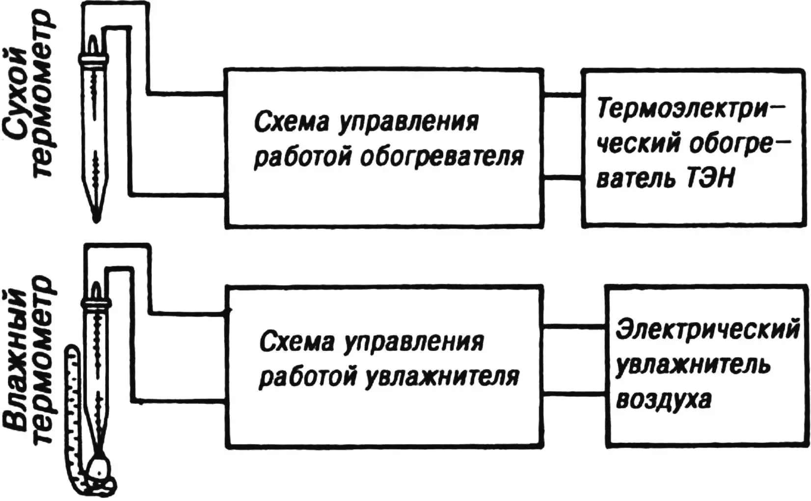
The DRY thermometer requires no “maintenance.” The desired temperature level is set with the standard magnetic device, and everything else is done by elementary automation based on the expansion of bodies (in this case, mercury) when heated and their contraction when cooled. Being electrically conductive by nature, the mercury column inside the glass bulb closes or opens the electric circuit, switching the heater on or off and thereby maintaining the ambient air temperature at the set level.
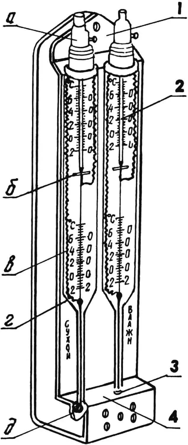
1 — plastic housing; 2 — mercury electrocontact thermometer TPK (2 pcs.); 3 — water-soaked gauze sleeve (present only on the WET thermometer); 4 — small vessel with water; a — magnetic adjusting device, b — movable electric contact; c — scale, d — cylindrical part of the thermometer’s glass body, e — glass bulb with mercury
The WET thermometer is a bit more “finicky”: for proper operation, the sleeve on its mercury bulb must never dry out. One has to watch this and, when necessary, top up water in the small vessel. Obeying the immutable laws of physics, water evaporates from the sleeve surface according to the relative humidity of the air, thereby cooling the mercury in the WT bulb.
This means that from the difference between the DRY and WET thermometer readings one can judge air humidity. Moreover, one can monitor the state of the environment and, if humidity deviates from the desired “norm,” switch an electric humidifier on or off. Automatic performance of this responsible function is provided by the electric contact set by the magnetic device of the WET thermometer according to the psychrometric table.
Psychrometric table
| Dry thermometer readings, °C | Wet thermometer readings, °C | |||||||||||||||||||
|---|---|---|---|---|---|---|---|---|---|---|---|---|---|---|---|---|---|---|---|---|
| 10 | 11 | 12 | 13 | 14 | 15 | 16 | 17 | 18 | 19 | 20 | 21 | 22 | 23 | 24 | 25 | 26 | 27 | 28 | 29 | |
| 10 | 100 | |||||||||||||||||||
| 11 | 88 | 100 | ||||||||||||||||||
| 12 | 78 | 89 | 100 | |||||||||||||||||
| 13 | 69 | 79 | 89 | 100 | ||||||||||||||||
| 14 | 60 | 70 | 79 | 90 | 100 | |||||||||||||||
| 15 | 52 | 61 | 71 | 80 | 90 | 100 | ||||||||||||||
| 16 | 46 | 54 | 63 | 71 | 81 | 90 | 100 | |||||||||||||
| 17 | 39 | 47 | 55 | 64 | 72 | 81 | 90 | 100 | ||||||||||||
| 18 | 34 | 41 | 49 | 56 | 65 | 73 | 82 | 91 | 100 | |||||||||||
| 19 | 29 | 36 | 43 | 50 | 58 | 66 | 74 | 82 | 91 | 100 | ||||||||||
| 20 | 24 | 30 | 37 | 44 | 51 | 59 | 66 | 74 | 83 | 91 | 100 | |||||||||
| 21 | 20 | 26 | 32 | 39 | 46 | 53 | 60 | 67 | 75 | 83 | 91 | 100 | ||||||||
| 22 | 16 | 22 | 28 | 34 | 40 | 47 | 54 | 61 | 68 | 76 | 84 | 92 | 100 | |||||||
| 23 | 13 | 18 | 24 | 30 | 36 | 42 | 48 | 55 | 62 | 69 | 76 | 84 | 92 | 100 | ||||||
| 24 | 10 | 15 | 20 | 26 | 31 | 37 | 43 | 49 | 56 | 63 | 70 | 77 | 84 | 92 | 100 | |||||
| 25 | 7 | 12 | 17 | 22 | 27 | 33 | 38 | 44 | 50 | 57 | 63 | 70 | 77 | 84 | 92 | 100 | ||||
| 26 | 5 | 9 | 14 | 19 | 24 | 29 | 34 | 40 | 46 | 52 | 58 | 64 | 71 | 78 | 85 | 92 | 100 | |||
| 27 | 3 | 7 | 11 | 16 | 21 | 25 | 30 | 36 | 41 | 47 | 52 | 58 | 65 | 71 | 78 | 85 | 92 | 100 | ||
| 28 | 1 | 5 | 9 | 13 | 18 | 22 | 27 | 32 | 37 | 42 | 48 | 53 | 59 | 65 | 72 | 78 | 85 | 93 | 100 | |
| 29 | 3 | 7 | 11 | 15 | 19 | 24 | 28 | 33 | 38 | 43 | 49 | 54 | 60 | 66 | 72 | 79 | 86 | 93 | 100 | |
| 30 | 1 | 5 | 9 | 13 | 17 | 21 | 25 | 30 | 34 | 39 | 44 | 50 | 55 | 61 | 67 | 73 | 79 | 86 | ||
| 31 | 3 | 7 | 10 | 14 | 18 | 22 | 27 | 31 | 36 | 40 | 45 | 50 | 56 | 62 | 67 | 73 | 80 | |||
| 32 | 5 | 8 | 12 | 16 | 20 | 24 | 28 | 32 | 37 | 41 | 46 | 51 | 57 | 62 | 68 | 74 | ||||
| 33 | 7 | 10 | 14 | 17 | 21 | 25 | 30 | 33 | 38 | 42 | 47 | 52 | 58 | 63 | 69 | |||||
| 34 | 5 | 8 | 12 | 15 | 19 | 22 | 26 | 30 | 34 | 39 | 43 | 48 | 53 | 58 | 64 | |||||
| 35 | 7 | |||||||||||||||||||
| 36 | 5 | |||||||||||||||||||
| 37 | 4 | |||||||||||||||||||
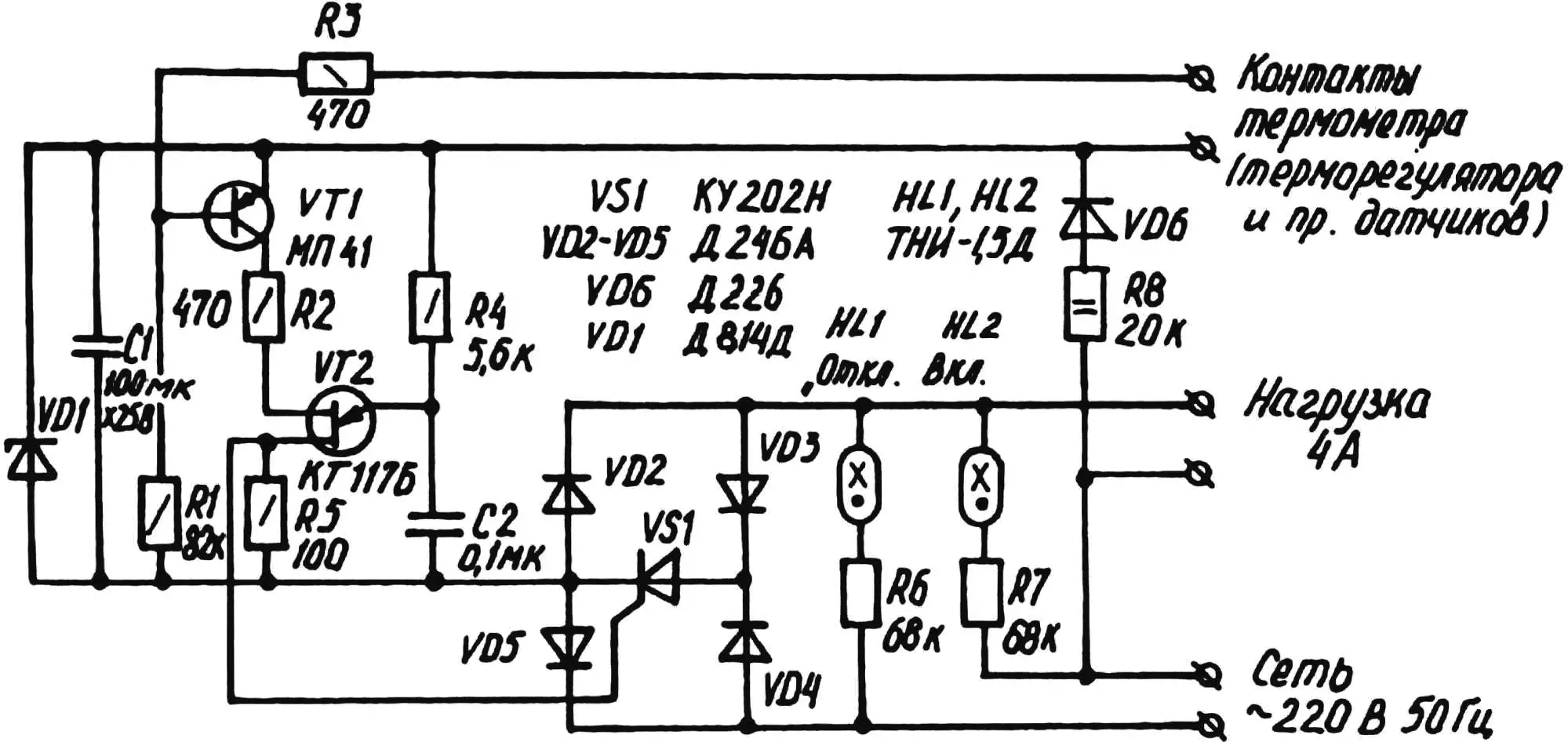
Each thermometer has its own control subblock. However, they are built according to the same basic electrical circuit using four D247 diodes, a D226 diode, a KU202 thyristor, a D814D Zener diode, and two transistors: MP41 and KT117B. Built into modern household appliances, such devices work reliably with various sensors and are already well known to a wide readership, so dwelling now on the details of their operation is hardly worthwhile.
A different matter is the algorithm for working with the system itself. For automatic maintenance of the required air humidity, one must first look at… the DRY thermometer and, having determined the established temperature (tdt) from the scale, memorize its value. Then the same should be done for the WT.
Having obtained the initial data, one can turn to the psychrometric table. Having found on it the value of tdt and then twt, at the intersection of the horizontal and vertical lines one should determine the established air humidity value ψ.
In particular, when tdt = 20 °C and twt = 15 °C, then ψ = 59%. And if tdt = 25 °C and twt = 21 °C, then ψ = 70%.
If the obtained humidity value is lower than required by the specifications, then, guided by the actual temperature tdt shown by the DRY thermometer, we find the humidity we need along the horizontal of the table and determine (along the vertical!) what values on the WT scale should correspond to it. By setting with the magnetic device the movable contact of the WET thermometer to the scale division equal to the required twt, we thereby set the necessary air humidity, which our obedient system will then maintain by connecting (disconnecting) the humidifier to (from) the household AC mains, and, if necessary, the heater.
For example, if tdt = 25 °C and ψ = 50% is needed, then twt = 18 °C. And if tdt = 29 °C and, say, 66% air humidity is required, then (according to the psychrometric table) the movable contact of the WET thermometer should be set to the scale division corresponding to twt = 24 °C.
Incidentally, the table is given in a somewhat abbreviated form. With it, air humidity can be determined only with a 10% adjustment, intended for the most common thermometers whose scale division step is 1 °C. For more precise setting of temperature and humidity, WT and DT with smaller error are needed; then using an extended psychrometric table will also be justified. For example, with a temperature scale having a division step of 0.1 °C, humidity setting accuracy can be brought to 1%!
“Modelist-Konstruktor” No. 8’2003, A. NARVATOV, engineer
Recommend to read
 THE “GAS” HANDLE
The cartridges for refilling gas lighters very durable case, it is a pity to throw away. Tried to find them a different application. The most successful, I think, is to make handles for... SIGNALLER OF BITE
Recently, widespread quartz alarm clock made in China, characterized by a relatively high ring volume and cheapness. If the watch is out of order, but the alarm clock still works, it can...
