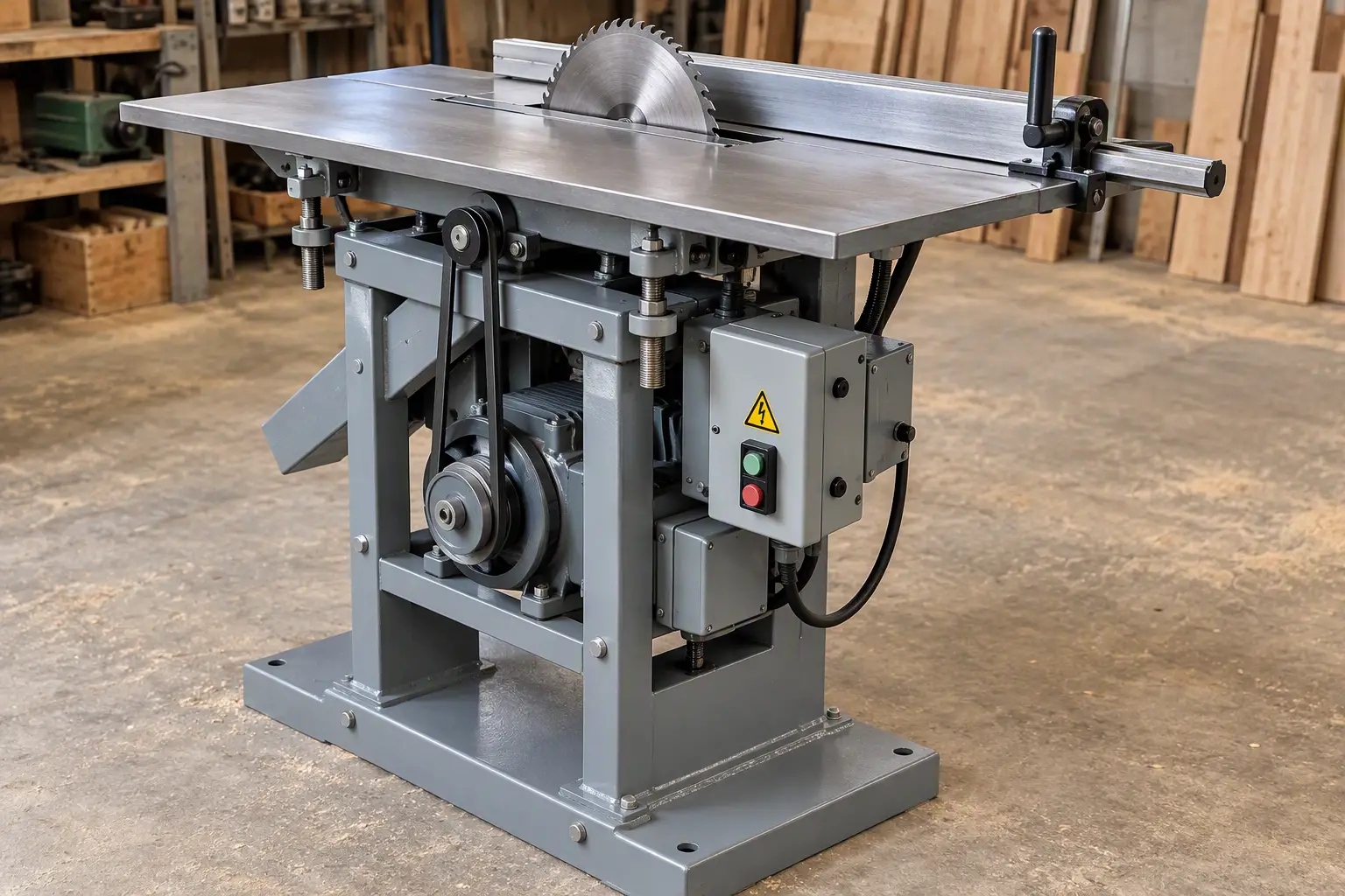
The woodworking machine presented to the readers’ judgment I designed myself, fabricated with my own hands, and now successfully use when building a house on my plot. I am becoming convinced how successful the design turned out: compact, technologically sound, and, I believe, quite suitable for “replication.” The machine is so simple that an overly detailed specification for making it is hardly necessary. All fastening points are freely accessible. So if desired, the design can easily be disassembled and, after being transported in a car trunk, reassembled in a new place in about thirty minutes.
The proposed version of a universal woodworking machine has load-bearing elements made of steel angle and sheet steel. Although I know: an experienced DIY builder will have no trouble finding a suitable substitute for these materials from whatever is at hand. Of course, while making maximum use of the engineering solutions that ensure compactness and ease of assembly and disassembly.
Take the welded assemblies and parts, for example. There are not many of them. First of all, there is the support base made of 50×50 mm steel angle. Next comes the frame for mounting the L-shaped table posts and the bearing units of the driven shaft with the machine’s working tools. It is made of 60×60 mm steel angle. Welding work is also required when rigidly fixing the sleeves of the L-shaped posts to the table top, making the fence/stop, and fabricating a special pivoting platform for the electric motor.
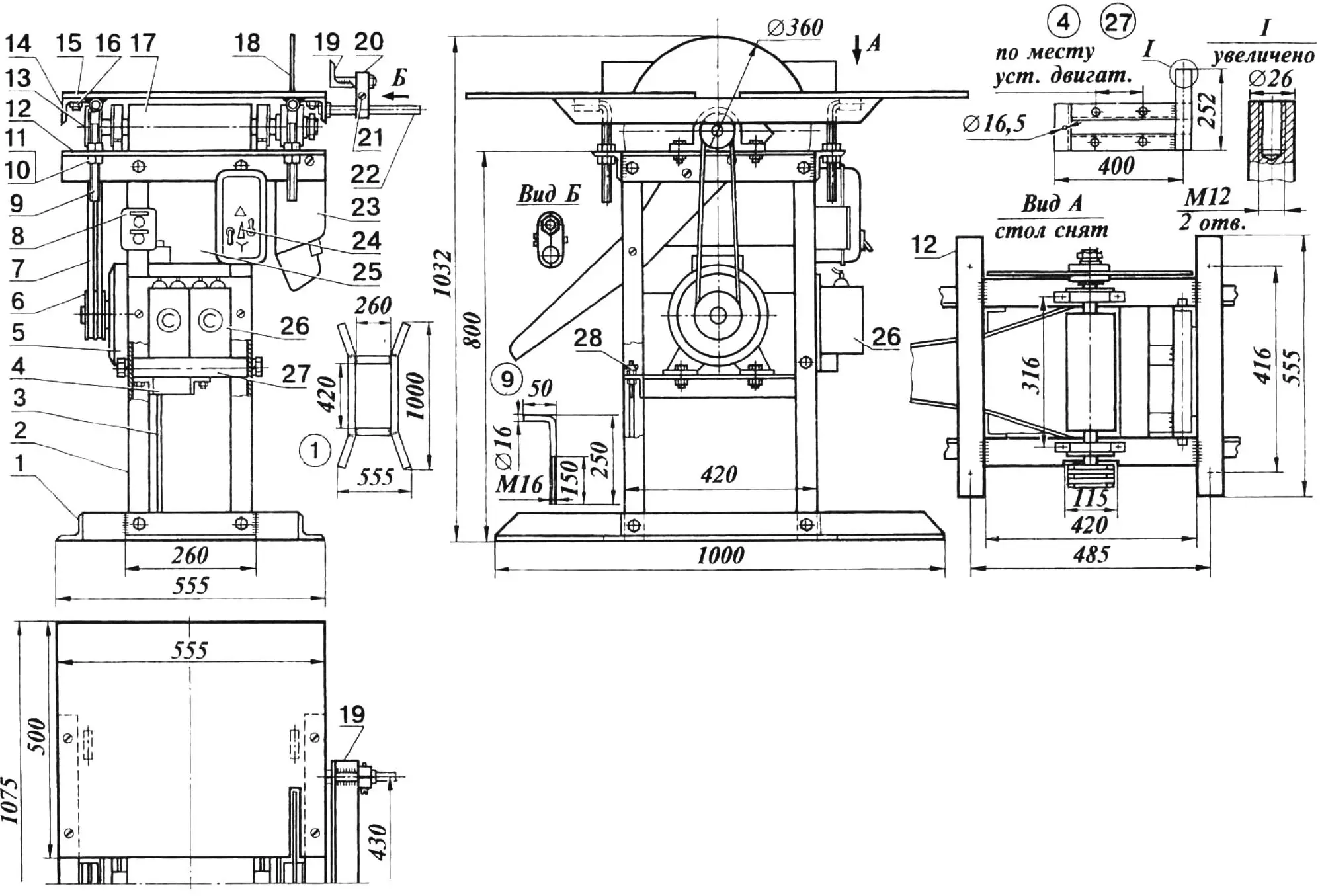
1 — support base, 2 — leg (steel angle 40×40, L800, 4 pcs), 3 — belt-drive tension rod (steel bar Ø16, L350 with M16 thread on the ends), 4 — motor pivoting platform, 5 — three-phase asynchronous electric motor AIR100S4U3, 6 — two-groove driving pulley (dp 100), 7 — V-belt (2 pcs), 8 — control panel with “Start” and “Stop” buttons, 9 — table post (4 pcs), 10 — M16 adjusting nut with locknut (4 sets), 11 — Grover washer (4 pcs), 12 — frame, 13 — two-groove driven pulley (dp 50). 14 — table longeron (steel angle 50×50, L700, 2 pcs), 15 — composite table top (steel sheet 555×500, s6, 2 pcs), 16 — M12 countersunk screw (22 pcs), 17 — rotary planer assembly, 18 — circular saw blade, 19 — fence/stop, 20 — composite clamp (2 pcs), 21 — M8 screw (2 pcs), 22 — guide with M16 thread on the end (2 pcs), 23 — sawdust chute (aluminum sheet, s3), 24 — magnetic starter with a switch (“Star” — “Delta”) and two switches, 25 — chip chute (aluminum sheet, s3), 26 — capacitor 100 µF × 400 V (2 pcs), 27 — motor platform axle, 28 — M16 wing nut.
The latter deserves a special note. It is welded from pieces of 40×40 mm steel angle and a rod in whose ends an internal M12 thread is cut. The rod serves as the platform’s pivot axle; it is inserted between the posts and secured on both sides with M12 bolts. The three-phase asynchronous motor AIR100S4U3 with a 100-mm two-groove pulley is mounted on the platform using four bolts with nuts and Grover washers.
Tension in the V-belt drive is adjusted by tightening the wing nut on the rod that passes through a hole in the platform, followed by locknutting.
The support base, the frame, and four posts made of 40×40 mm steel angle, fastened together with M20 bolts, form the bed. Chutes for sawdust and chips made from sheet aluminum are screwed to it, along with other assemblies and parts, including the motor starting and control equipment.
The table top consists of two identical 6-mm steel plates fastened to each other by longerons using M12 countersunk screws and locknuts. As already noted, four sleeves are welded to the underside of the top, in which the L-shaped posts can rotate. As for the fence/stop, it is mounted on guides using composite clamps and M8 screws.
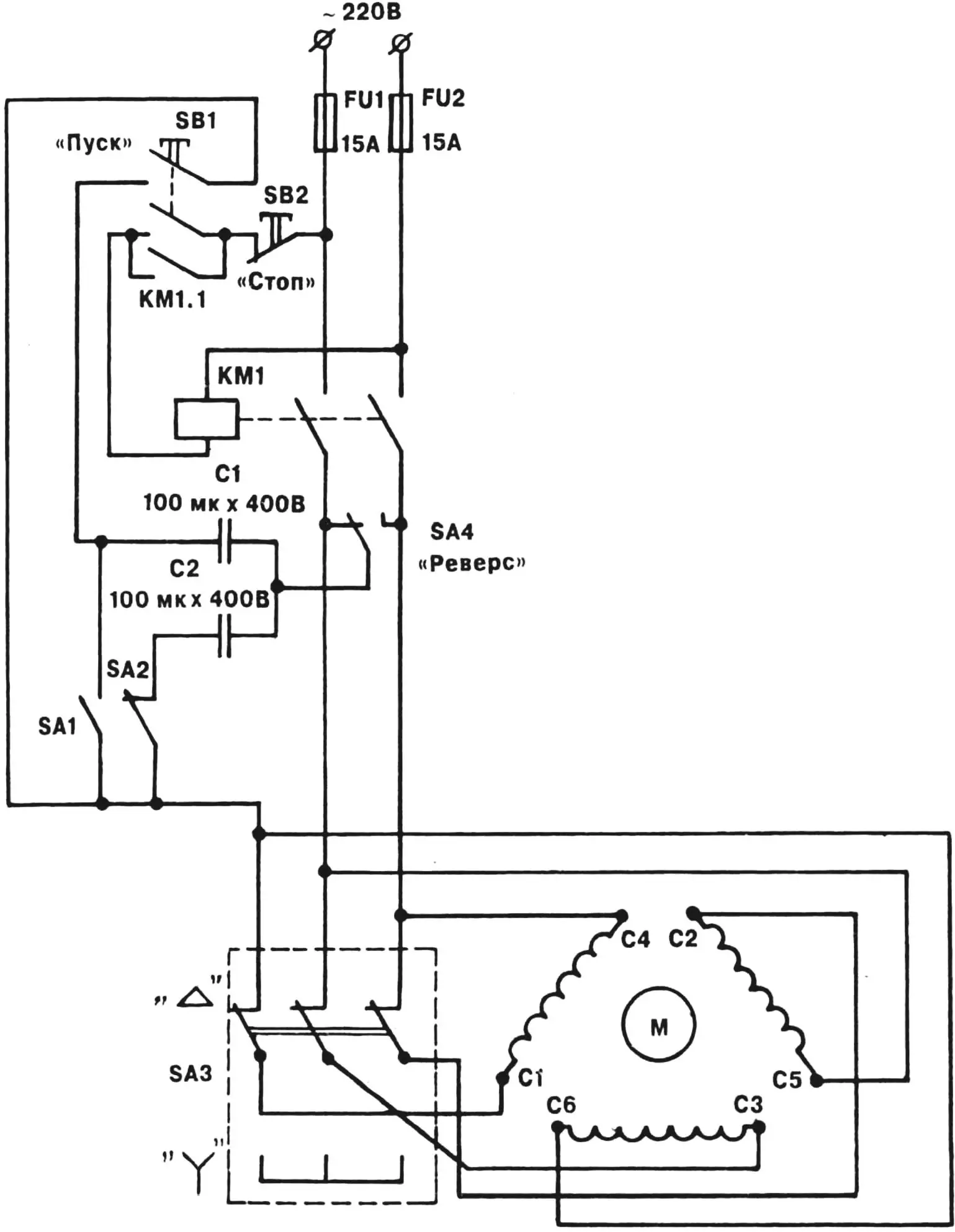
A few words about the motor. Since the machine uses a three-phase AIR100S4U3 (3 kW, 1410 rpm), phase-shifting capacitors — starting and running — had to be introduced to connect it to a single-phase network. And for the most efficient use, provision was made for connecting the windings either in “star” or in “delta.” The first of these modes (conventionally marked “Y”) is recommended for sawing and planing under reduced load (when the boards are not too thick). The “Start” button is pressed here if SA1 is off, SA2 is on, and SA3 is in the “Y” position. Then the magnetic starter will operate and, by interlocking SB1, will provide a reliable supply of voltage to the motor windings.
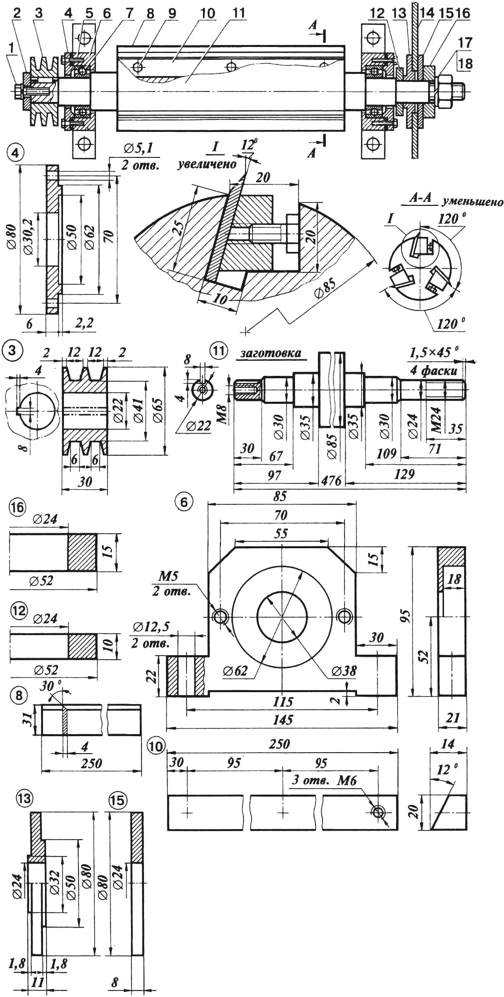
1 — M8 bolt with Grover washer, 2 — clamping washer, 3 — two-groove driven pulley, 4 — bearing-unit cover (St5, 2 pcs), 5 — M5 bolt (4 pcs), 6 — bearing-unit housing (St5, 2 pcs), 7 — ball bearing 206 (2 pcs), 8 — planer knife (tool steel, 3 pcs), 9 — M6 spacer bolt (9 pcs), 10 — clamping strip (St3, 3 pcs), 11 — driven shaft (steel 45), 12 — spacer ring (St3), 13 — profile washer (St3), 14 — circular saw blade, 15 — tightening washer (St3), 16 — tightening ring (St3), 17 — M24 nut, 18 — Grover washer.
The mode conventionally marked “Δ” is operation at increased power. It is switched to only after the electric motor, having thoroughly accelerated, has reached the required speed in the “Y” mode. Then the capacitance of the phase-shifting capacitor is boldly increased by additionally connecting another 100 µF with SA1. And only after that, without allowing strong starting currents, the windings are switched to “delta” by moving SA3 to the “Δ” position.
Stopping the motor is easy in either mode. It is enough to press the “Stop” button. Then the supply voltage to the magnetic starter coil winding is immediately cut off, and the starter de-energizes the electric motor.
As for switch SA4 “Reverse,” practice has shown that it need not be installed. The required direction of rotation is then obtained during commissioning by “swapping the ends” of one of the windings.
And one more remark about the operating features of the circuit under discussion. After the electric motor is stopped, both capacitors must be discharged. To do this, it is enough simply to… turn on SA1 and SA2.
It is now time to consider the operating features of the machine as a whole. This is best done by referring to the illustrations.
First of all — adjusting the cutting depth, as well as the thickness of the chip removed. The required results are achieved here… by turning nuts. Special adjusting ones, followed by locking with the lower nut.
Changing the table tilt (when sawing at an angle other than a right angle) is done by simply raising (or lowering) the posts (on the opposite side of the saw blade) to the required height. Optimal shaft speeds (1500 rpm for sawing and about 3500 rpm for planing the stock) are obtained by appropriately selecting the diameters of the driving and driven pulleys.
Other capabilities of the machine? They depend directly on which tool is on the working shaft. For example, using various cutters, you can successfully machine grooves and rabbets. By replacing the saw blade with a cutoff wheel, you get a reliable mechanical metal cutter. And with a grinding wheel installed — a tool-sharpening machine.
But all of this requires care. And, of course, the strictest, unwavering observance of safety rules. In particular, when mounting the shaft on the bed frame, it must be rigidly secured without misalignment. After tightening the bolts on one support first, make sure the other has not lifted above the frame and has not been pressed against it excessively. Then approach tightening the bolts on the second support with the same caution. Correct any misalignment at once by placing metal shims under the supports. Pack the bearings with high-melting grease. Make sure that sawdust and chips never get into them.
Treat the planer with no less care. The knives of this working tool must be securely fastened with bolts. It is worth remembering that when the planer is not in use, it must be covered with a special metal guard (conventionally not shown in the drawing).
The circular-saw mounting nuts must invariably have Grover washers to avoid any surprises, and the other threaded joints also need proper tightening. Before working on the machine, check how well everything is secured. Make sure the V-belt drive is reliable by turning the shaft several times by the drive belt. The shaft should rotate freely, without binding. And only then can you begin work.
“Modelist-Konstruktor” No. 3’97, B. POTAPOV
Recommend to read
 “MOUSE” IS THE YOUNGER BROTHER OF “CHEBURASHKA”
Flipping through the 1975 edition of Modelist, I noticed an article in No. 3 about the Cheburashka car, built by young technicians from Tbilisi. I liked the car and decided to make one for... KAMOV Ka-226
Universal multipurpose coaxial helicopter Ka-226 can be used in the transport, medical, agricultural and patrol variants. The multiplicity of application is provided not by modifying the...
