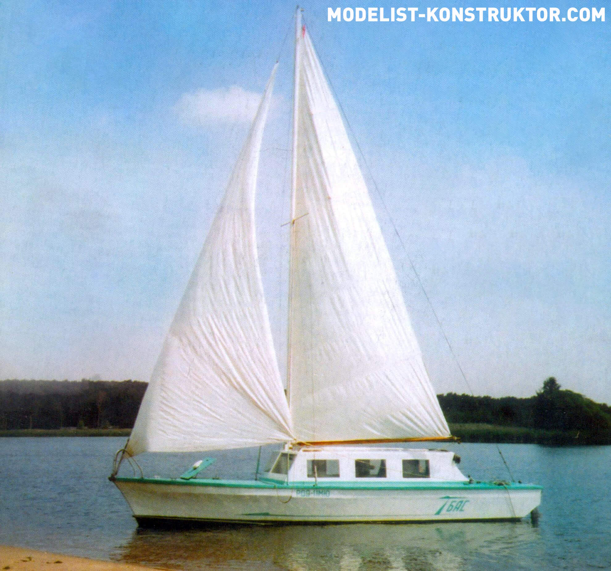
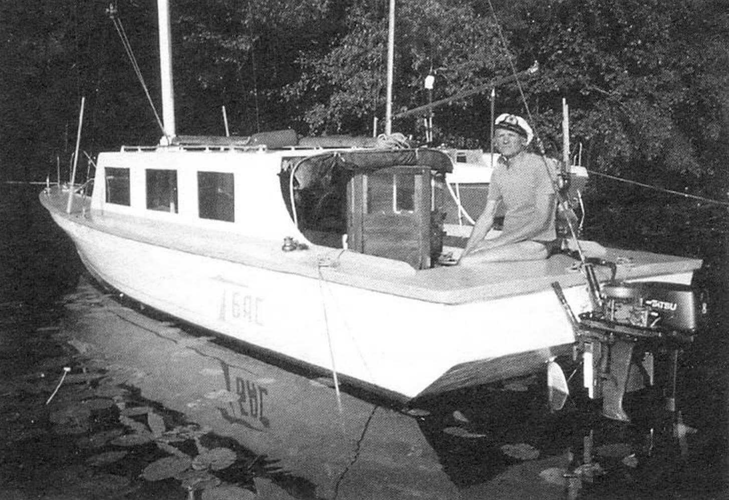
The motor-sailing vessel (SMS), which will be discussed, was built on the basis of the finished hull of an existing model of a torpedo boat, made on a scale of 1:4. I got the hull of the model, 7.4 m long along the waterline, at almost a bargain price, when in the mid-1980s, during another environmental campaign, the banks of the Pirogovskoye reservoir near Moscow were cleaned.
The reconstruction of the boat model into a motor-sailing vessel did not require large labor costs and financial investments. But I was, one might say, lucky with the case. For those who want to build the same or similar one, I provide a description of the design of the entire body with explanatory drawings.
First, a few words about the technology of building a ship from scratch.
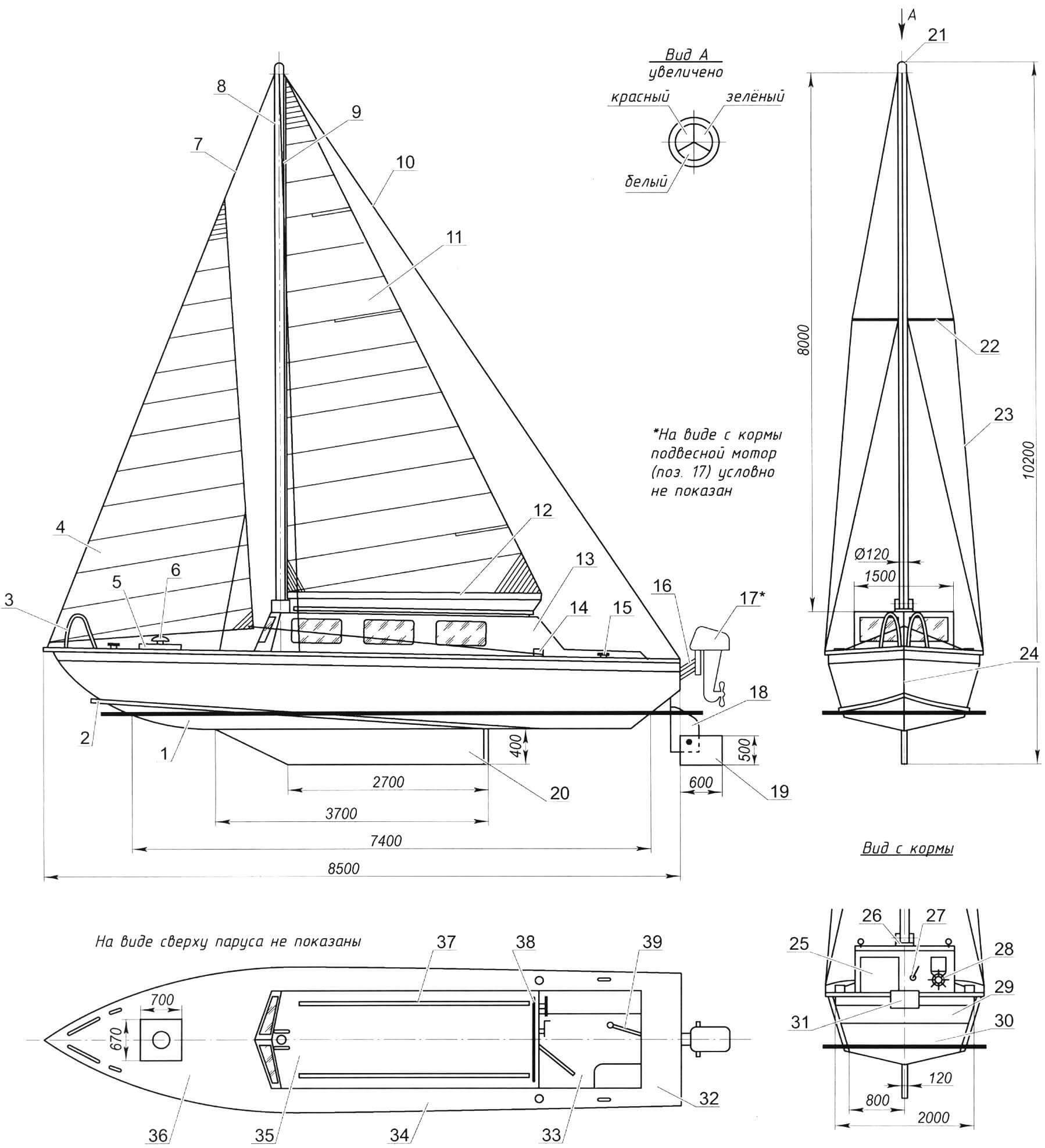
1 — body (s6 plywood, 2-layer fiberglass); 2 — splash deflector; 3 — bow rail (pipe Ø20, 2 pcs.); 4 — staysail sail; 5 — forepeak hatch; 6 – ventilation fungus; 7 – forestay; 8 — mast (duralumin pipe Ø120×114, L8000); 9 — mast lip seal; 10 — backstay; 11 — mainsail sail (purchased product, from a sports yacht of the “Dragon” type); 12 — mainsail boom (oak, timber Ø80); 13 — deckhouse (s10 plywood, 2-layer fiberglass); 14 — jib winch (2 pcs.); 15 — duck (4 pcs.); 16 — pantograph for mounting the outboard motor; 17 — outboard motor; 18 — stationary rudder; 19 — folding rudder; 20 — false keel; 21 — top-end three-color flashlight; 22 – yard; 23 — side shroud (2 pcs.); 24 – stem; 25 — door to the wheelhouse; 26 – steps; 27 — winch for the boom; 28 — steering wheel; 29 — vertical part of the transom; 30 — inclined part of the transom; 31 — outboard motor pantograph cradle; 32 – south; 33 — cockpit; 34 – waist; 35 — cabin roof; 36 — tank; 37 — side handrail (rough Ø20, 2 pcs.); 38 — main boom shoulder strap (duralumin, strip 1500x60x6); 39 — steering tiller
Before manufacturing each frame, proceed as follows. First, it is drawn to life size on a plaza from a suitable sheet of plywood. The frames are assembled from individual elements made of 20 mm thick pine boards, which are fastened together with overlaps or gussets, epoxy glue, screws, and, if necessary, additional bolts.
To assemble the ship’s hull from individual elements, a slipway is mounted. A keel beam is installed on the slipway and pre-fabricated frames are attached to it with epoxy glue and screws. The frames are connected by longitudinal load-bearing elements. Next, the hull is sheathed.
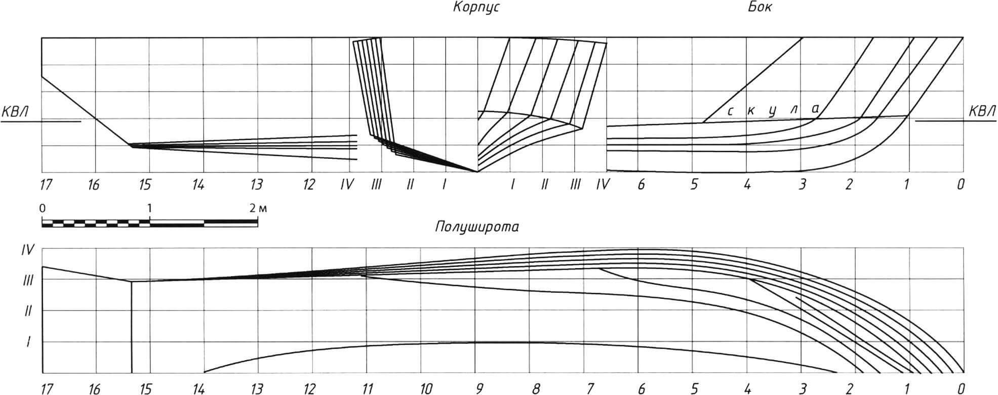
Describing the vessel, first of all I will note that it is a cabin type. Its entire power structure is made of wood, and the skin is made of baked plywood covered with a thin layer of fiberglass.
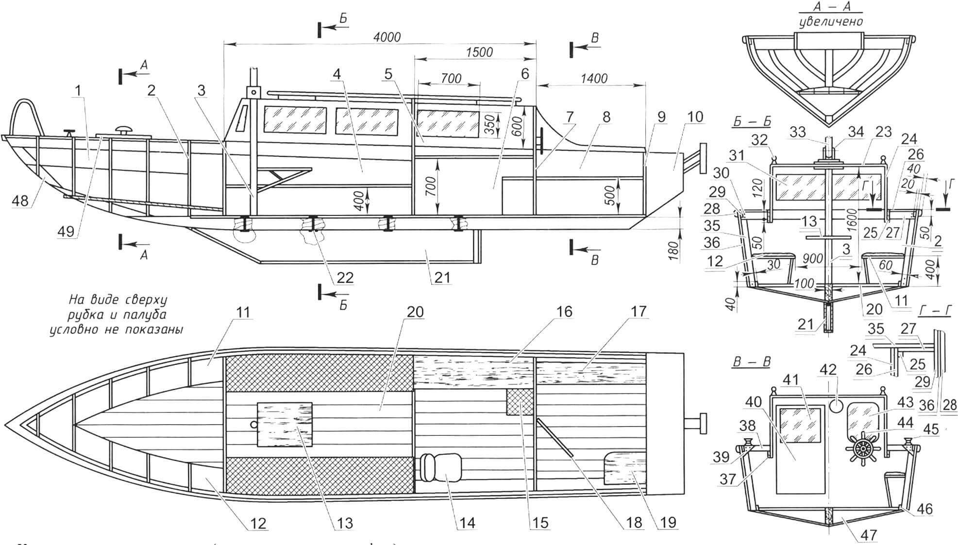
1 — forepeak; 2 – watertight bulkhead; 3 — mast pillars; 4 — cabin; 5 — bulkhead with opening; 6 – galley; 7 — external bulkhead with door; 8 — cockpit; 9 — sliding bulkhead of the afterpeak; 10 — afterpeak; 11 — sofa-locker for sail; 12 — sofa-locker for life jackets; 13 — folding table; 14 — chair; 15 – bank; 16 – desktop; 17 — bank-locker for the battery and gas cylinder; 18 — door to the wheelhouse; 19 — bank-locker for an anchor with a rope; 20 – flooring; 21 – false keel; 22 — fastening the false keel to the keel (bolt M20x185, 4 pcs.); 23 — cabin roof (moisture-resistant plywood s12, 2 mm layer of fiberglass); 24 — cabin wall (moisture-resistant plywood s12, 2 mm layer of fiberglass); 25 — carlings (board 150×20); 26 — waist deck (lining board s20, 2 mm layer of fiberglass); 27 — beams (larch, board 150×20); 28 — external fender beam (larch, timber 50×40); 29 — internal fender beam (larch, timber 60×20); 30 — coupling bolt M8 (4 pcs.); 31 — wheelhouse windshield (triplex s6, 2 pcs.); 32 — handrail (duralumin pipe Ø20, 2 pcs.); 33 — mast; 34 — mast steps; 35 — frame; 36 — side trim; 37 — backing block (pine, block 30×30); 38 — half-beam (larch, timber 60×20); 39 — bracket (plywood s6); 40 — door to the wheelhouse; 41 — window in the door (plexiglass s6); 42 — manual winch for the boom halyard; 43 — rear cabin window (triplex s6); 44 — steering wheel; 45 — manual winch for jib halyard (2 pcs.); 46 — zygomatic stringer (2 pcs.); 47 — flor (2 pcs.); 48 — stem; 49 — hatch to the forepeak
The ship is divided into five compartments. The first of them – the forepeak – is separated from the subsequent ones by a waterproof (“blind”) bulkhead located on the sixth frame. To access the forepeak, there is a hatch in the forecastle deck, which is closed with a hinged lid measuring 700×670 mm, made of lining and covered with fiberglass fabric and epoxy resin. A ventilation fungus is mounted on the hatch cover.
The next compartment is the wardroom. There is a folding table attached to the pillar, along the sides there are two semi-soft sofa-lockers: one for sailing, the other for life jackets. With the table folded out, 4 people can rest in the cabin and 2 people in the forepeak (6 people in total).
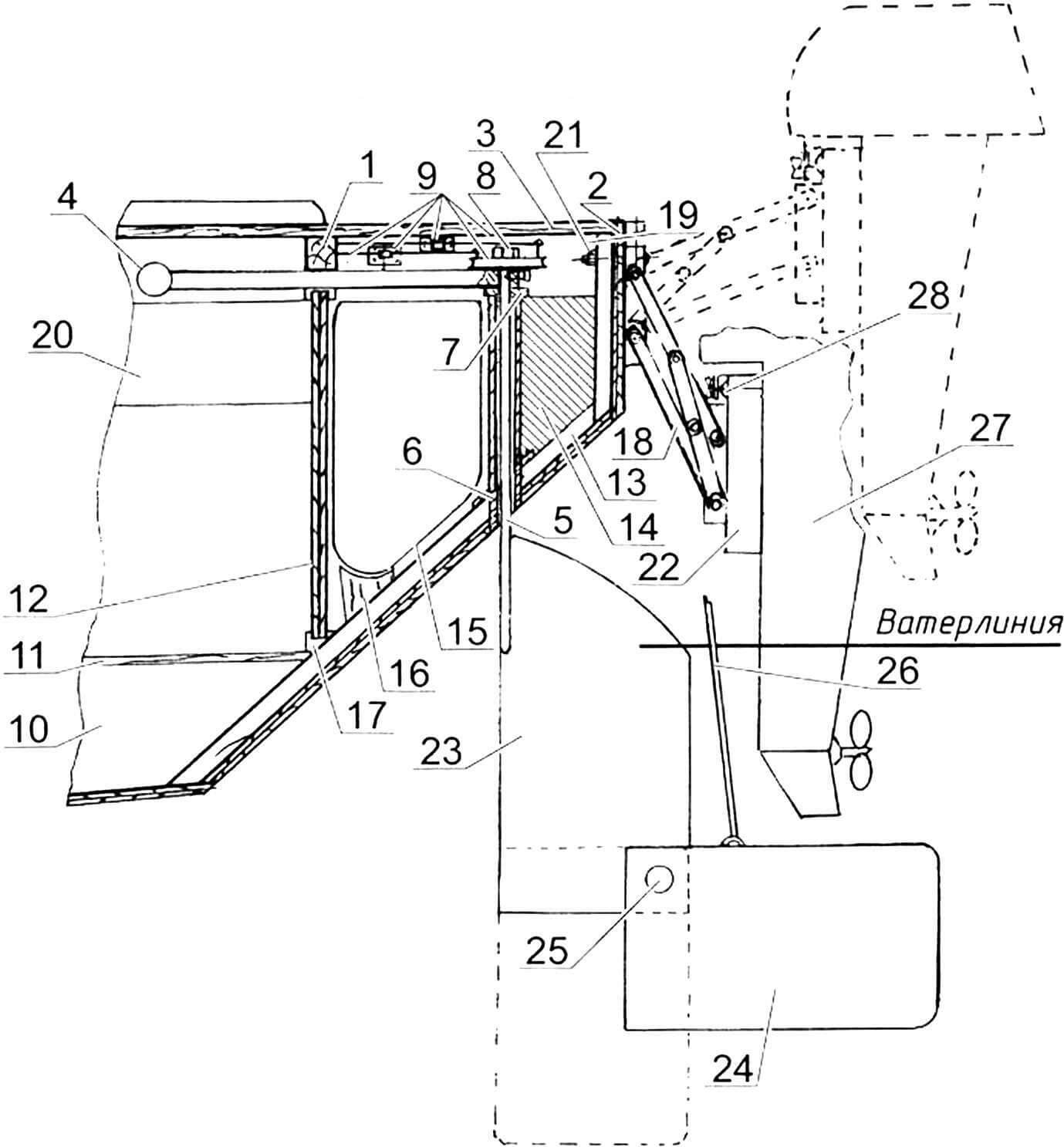
1 – beam (upper cross member) of the penultimate frame; 2 — transom; 3 – upper deck flooring; 4 — tiller (stainless steel, pipe Ø20 mm with an internal diameter of 8 mm with a stopper, bolt with a diameter of 10 mm); 5 — steering stock (steel, circle Ø29); 6 — baller pipe (stainless steel, pipe Ø31×29); 7 — washer (steel); 8 — bolt (steel, Ø16 mm, L100 mm) for attaching the tiller to the steering stock; 9 — transmission — a system of cables and pulleys (steel), for duplicating steering control through the steering wheel; 10 — keel block; 11 — flooring of the lower deck; 12 — sliding bulkheads (plywood, s6); 13 – the last frame – fascia (oak board with a section of 120×30 mm); 14 — thrust beam of the balloon line (oak, 100×60, attached with epoxy glue and screws to the last frame); 15 — fuel tank 180 l (duralumin); 16 — wooden stand for the fuel tank (attached to the frame with screws); 17 — guides for sliding bulkheads (wood); 18 — pantograph; 19 — steering compartment; 20 — cockpit; 21 — M8 fastening bolts for fastening the pantograph frames to the transom of the vessel and the under-engine plate (steel, L100 mm, 8 pcs.); 22 — sub-motor pantograph plate; 23 — rudder blade (stainless steel, plate 600x500x10); 24 — rudder blade (stainless steel, plate 600x500x10); 25 — steering wheel axis (steel bolt M10, L30); 26 — halyard for lifting the rudder; 27 — outboard motor; 28 – standard outboard motor clamp screw
The third compartment is the galley. In it, on the starboard side, there is a work desk with a gas stove. Gas is supplied through a hose from a five-liter cylinder installed in the next compartment – the cockpit. The table, closed with sliding doors, stores food and drinking water in two ten-liter canisters for long hikes. There are two chairs in the galley. In the bulkhead between the galley and the wardroom there is a large opening (1500 mm high and 900 mm wide) and the bulkhead is more of a portal covered with a curtain. The cabin and galley are located in the wheelhouse, and both compartments can be sealed by closing the front door.
Next comes the cockpit measuring 1.5 x 1.5 m. From here the sails and the ship itself are controlled. There are two locker seats here: one on the starboard side – along the entire length of the cockpit (it stores a gas cylinder, battery, water supply and four fenders) and a small one in the left rear corner (the anchor and rope are removed here, the anchor is raised manually). This compartment is open, but if necessary, in rain or bad weather, it is covered with a tarpaulin awning.
The last compartment is the afterpeak, small. It is separated from the cockpit by a sliding partition. Behind it is a 180-liter fuel tank. The top of the afterpeak is covered by a deck that forms the poop. Below deck are the steering cables and pulleys, as well as the rudder stock and tiller, which opens into the cockpit.
I can’t say what kind of propulsion the boat itself was designed for, but the model had a water jet. At first, I planned to install a stationary engine on the boat, only replacing the propulsion with a propeller.
But soon a state program was adopted to protect water bodies from pollution, which obligated owners of small vessels to convert motor boats into sails. To do this, it was necessary to rebuild the hull of the boat model, bringing it as close as possible to the design of the yacht hull.
In the front part of the hull there was a forecastle – a 200-mm elevation above the level of the rest of the deck. I left him. Everything else: the pilothouse, the deck from the forecastle to the stern was removed. The stationary engine was also dismantled.
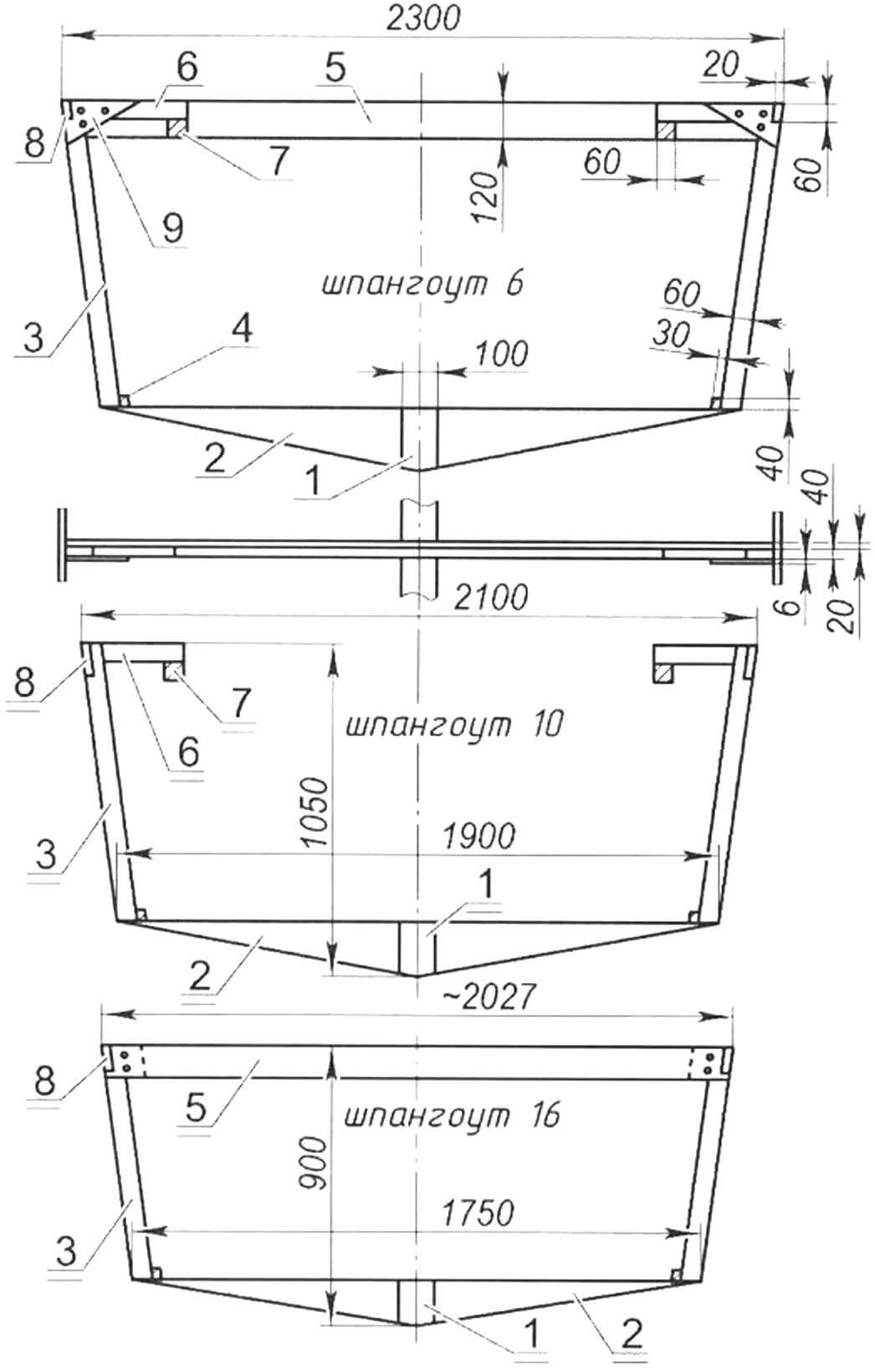
On both sides, from the stern to the forecastle, there was a kind of shearstrake – an upper reinforced belt of the sides. To do this, I increased the frames by 180 mm (to the level of the forecastle) with overlapping larch bars using epoxy glue and tightened them additionally with bolts. The upper ends of the frame extensions were combined with an angular (between the side and the deck) stringer with a section of 60×20 mm (a larch board about 6000 mm long), inserting it into pre-cut corresponding grooves in the frames using epoxy glue and screws.
A vertical transom made of epoxy plywood 10 mm thick was mounted on the fascia – the last aft frame of the model’s hull. They (the frame and transom) were also converted into a “yacht” stern. From the transom I left a rectangle 300 mm high at the top. Another sheet of the same plywood, pre-cut according to the profile of the sides and bottom, was attached to the lower edge of the transom at an angle of 60° inside the vessel from the vertical. I also preliminarily remade the lower part of the stern frame.
The penultimate frame was closed at the top with a cross-beam (a larch board with a cross-section of 100×20 mm and a length of 2000 mm), fastening them with epoxy glue and screws. From this cross member to the forecastle beam, I installed a pair of longitudinal under-deck beams on both sides, symmetrically at a distance of 750 mm from the centerline plane – carlings made of larch boards with a cross-section of 150×20 mm and a length of 5500 mm. I attached the carlings to the beams using epoxy glue and screws using wooden blocks installed at the ends of the carlings. Between the carlings and the extended parts of the frames on both sides I installed half-beams – short wooden cross members, attaching them to both elements with epoxy glue and screws. Then I attached the deck flooring of the waist (lining with a cross-section of 100×20 mm and a length of 6000 mm – from the forecastle to the transom) to the half-beams with epoxy glue and galvanized screws. The remaining gap between the carlings from the penultimate cross member to the transom was also covered with the same clapboard (deck flooring), but in short 500 mm sections.
On the extended parts of the frames from the forecastle to the transom, a shearstrake was installed on the outside on both sides – the upper (additional) reinforced belt of the side skin made of 6 mm plywood, 200 mm wide and 6 m long. It was made end-to-end with the existing skin and attached to it with epoxy glue, and to the frames – also with screws.
After that, along the perimeter, flush with the deck flooring, I attached an external fender made of larch with a cross-section of 50×40 mm to the corner stringer with epoxy glue and screws.
I provide descriptions of the above modifications to help those who may find themselves faced with the same need.
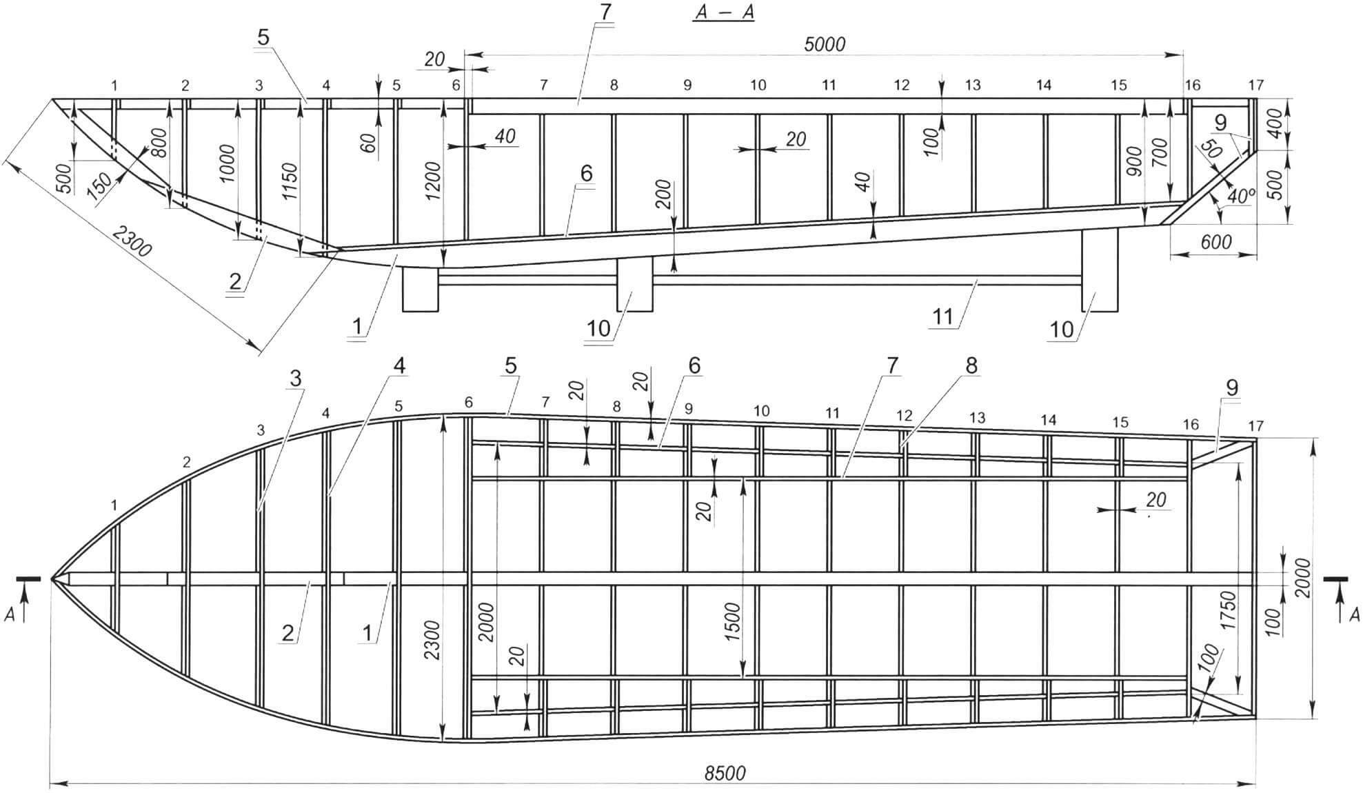
1 — keel (oak); 2 – stem; 3 — frame (larch); 4 — beams (larch); 5 — internal fender; 6 — zygomatic stringer (larch, timber 40×20, 2 pcs.); 7 — carlings (larch, board 100×20.2 pcs.); 8 — half-beam (larch); 9 – fascia; 10 — stand of the slipway; 11 — slipway beam
Inside the hull, I installed a keelson on the bottom and glued it with epoxy resin – a beam made of oak timber with a cross-section of 180×100 mm and a length of about 6.5 m, to which I attached the floras from all the frames. On the flora I laid a flooring of 20 mm larch boards (board width 150 mm).
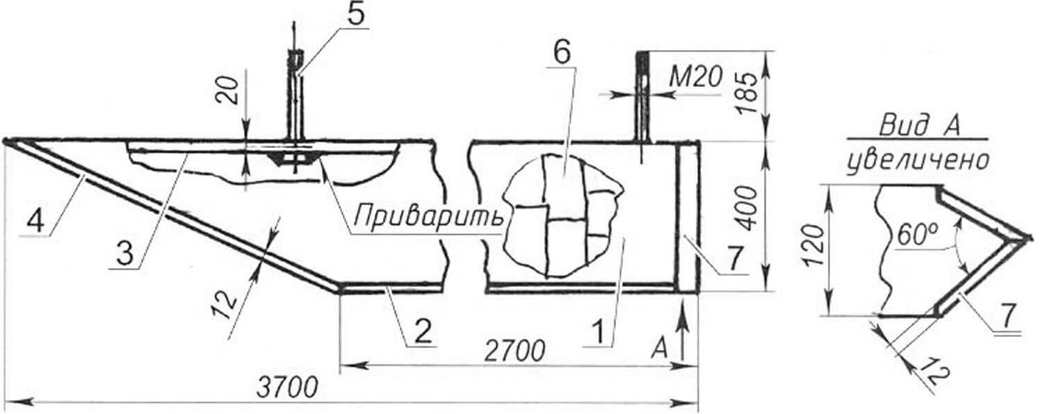
1 — wall (2 pcs.); 2 – bottom; 3 — ceiling (steel strip s20); 4 — ski; 5 — M20 bolt (4 pcs.); 6 — ballast m=350 kg (lead ingots); 7 – rear prismatic wall
A false keel with a length of 3700 mm and a height (depth) of 410 mm, made of 10 mm steel armor plate, is attached to the keel and keelson with four M16 steel bolts 250 mm long. The false keel is a welded narrow box 100 mm thick, with a cut in the front part at 30°. The box is welded to a steel plate measuring 3700×80 mm and 20 mm thick with four M16 bolts inserted into it for fastening to the keel (and keelson). The bottom is welded to the bottom of the box – a strip of armor steel (2700x100x10 mm). The weight of the box was 150 kg. But it might not be enough to ensure reliable stability of the vessel. Therefore, I decided to fill the false keel box with ballast. To do this, in a T-beam 115 mm wide, like in a trough, lead was melted over a fire and the frozen ingots with a total mass of 250 kg were placed in a false keel box. The rear opening of the box was closed (welded) with a prism (converging strips) made of steel sheet. After this, the false keel was brought to the hull, standing on a wooden slipway, and raised to the bottom with two jacks. Four M16 bolts were pressed with epoxy glue and inserted into pre-drilled corresponding holes in the keel and keelson, which ensured the tightness of the hull and the reliability of fastening the false keel.
1 – keel; 2 – flor; 3 — frame (futox); 4 — zygomatic stringer; 5 – beam; 6 – half beam; 7 – carlings; 8 — fender; 9 — bracket (plywood s6)
To install deckhouses on both sides, walls are attached to the carlings with epoxy glue and screws – sheets of bakelized plywood measuring 4000×700 mm and 10 mm thick to a height of 600 mm from the deck, and down to the edges of the carlings. Previously, the front edge of the walls was cut at 25° to the vertical and a frame made of a wooden block for the front windows was attached here.
Inside the cabin, a portal bulkhead (plywood) is installed vertically, the cabin roof frames are attached, on which the roof is laid (on epoxy resin and galvanized screws, board, lining 3500x100x15 mm). Three rectangular holes measuring 700×350 mm for portholes are cut in the side walls of the cabin. After this, pre-prepared windows made of organic glass 6 mm thick are installed on sealant and secured with bronze screws.
The rear entrance bulkhead of the cabin is installed with epoxy glue and galvanized screws (lining 1000x100x15 mm, 450x100x15 mm, height – 1585 mm). On the left side there is a door with the same window. A similar window is located on the right side of the bulkhead in front of the helmsman’s workplace.
As for finishing the body (or rather, preparing it for fiberglass coating), it is traditional for wooden products. The body parts are leveled (where required) with epoxy putty, sanded with sandpaper, vacuumed, wiped with acetone and covered with two layers of fiberglass with epoxy resin. Do not seal the entire body at once. It is more convenient to do this sequentially. For example, glue one or two longitudinal belts, after the glue has cured, treat them on the outside, and only then glue the next belt.
The final (surface) finishing of the fiberglass coating again includes sanding, removing dust with a vacuum cleaner and washing with acetone. Finally, the surface is primed and painted with enamel.
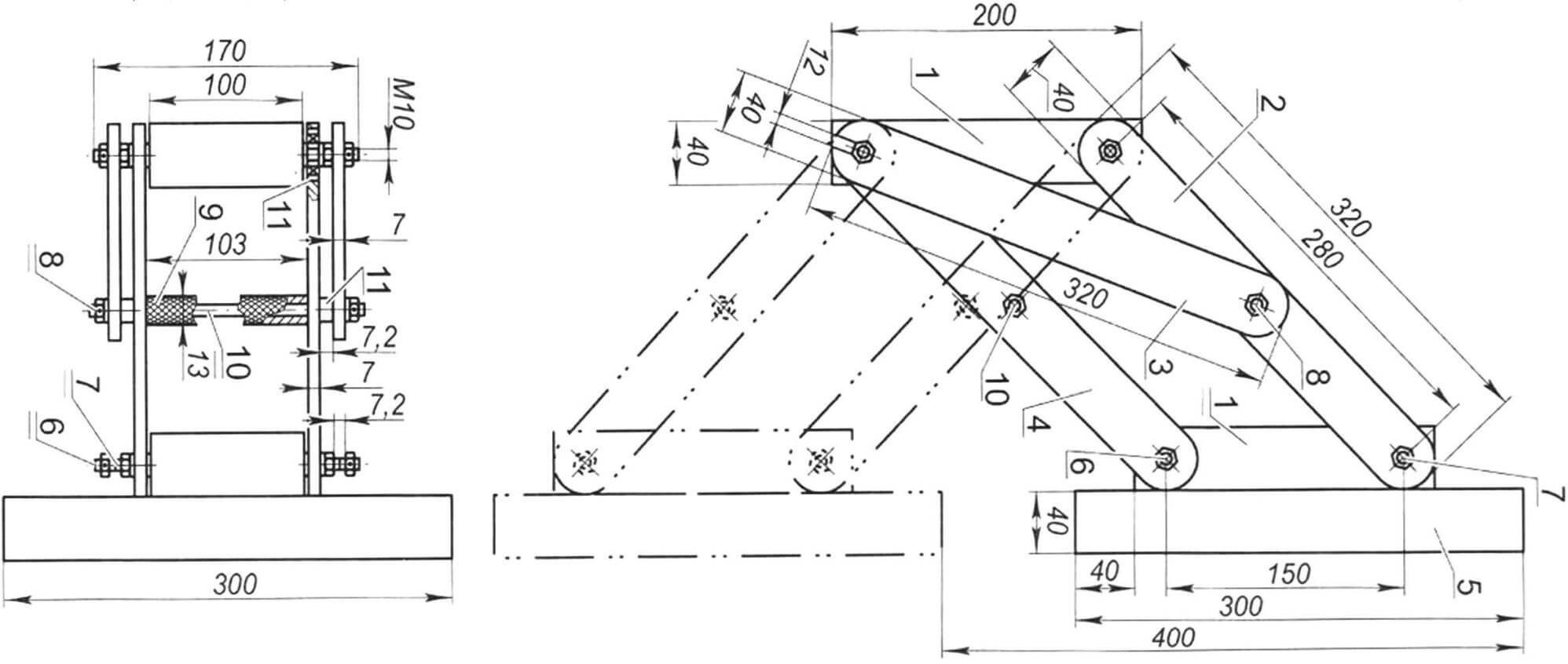
1 — bed (duralumin, plate 200×100, s40, 2 pcs.); 2 — lifting bracket (stainless steel, strip 320×40, s7, 2 pcs.); 3 — stop (stainless steel, strip 320×40, s7, 2 pcs.); 4 — support bracket (stainless steel, strip 320×40, s7, 2 pcs.); 5 — sub-motor plate (textolite, plate 300×300, s40); 6 — hinge support axis (pin M10x170, 4 nuts M10, 2 washers, 2 spring washers, 2 cotter pins, 2 sets in total); 7 — hinge axis (pin M10x150, 4 nuts M10, 2 washers, 2 spring washers, 2 cotter pins, 2 sets in total); 8 — handle axis (pin M10x170, 4 nuts M10, 2 washers, 2 spring washers, 2 cotter pins); 9 — handle (pipe Ø13×1.5 with external notch); 10 — support bracket tie (stud M10x160, 2 M10 nuts, 2 cotter pins); 11 — spacer sleeve (2 pcs.)
A pantograph is mounted on the transom, which, using a handle, allows you to set the outboard motor in the operating position “on the water” and in the non-operating position “out of the water” by moving the lower ends of the stops from the supporting axis of one plate to another when the boat is sailing or at rest.
The rudder blade is composite, its lower folding part (a stainless steel sheet measuring 500x600x10 mm) can be rotated around its axis and raised upward – either arbitrarily (in the shallows and from underwater obstacles) or with a drawbar (when mooring). The rudder can be controlled by a tiller or steering wheel through a system of flexible (cable) wiring and rollers.
On the roof of the cabin there are handrails installed along its entire length (a duralumin tube with an outer diameter of 20 mm) on duralumin holders and a boom shoulder strap.
According to the sail centering calculations, the mast had to be installed at a distance of 3.5 m from the bow of the boat – right on the roof of the wheelhouse. Here a step was mounted – a box measuring 150x150x150 mm from a 12-mm duralumin sheet with drilled holes in the side walls – 20 mm in diameter for fastening the mast when installing it with an M20 bolt 170 mm long through the corresponding hole at its end. Under the steps, inside the cabin, there is a pillar (titanium pipe with an outer diameter of 60 mm and a wall thickness of 5 mm) with an emphasis on the keelson and, accordingly, the keel.
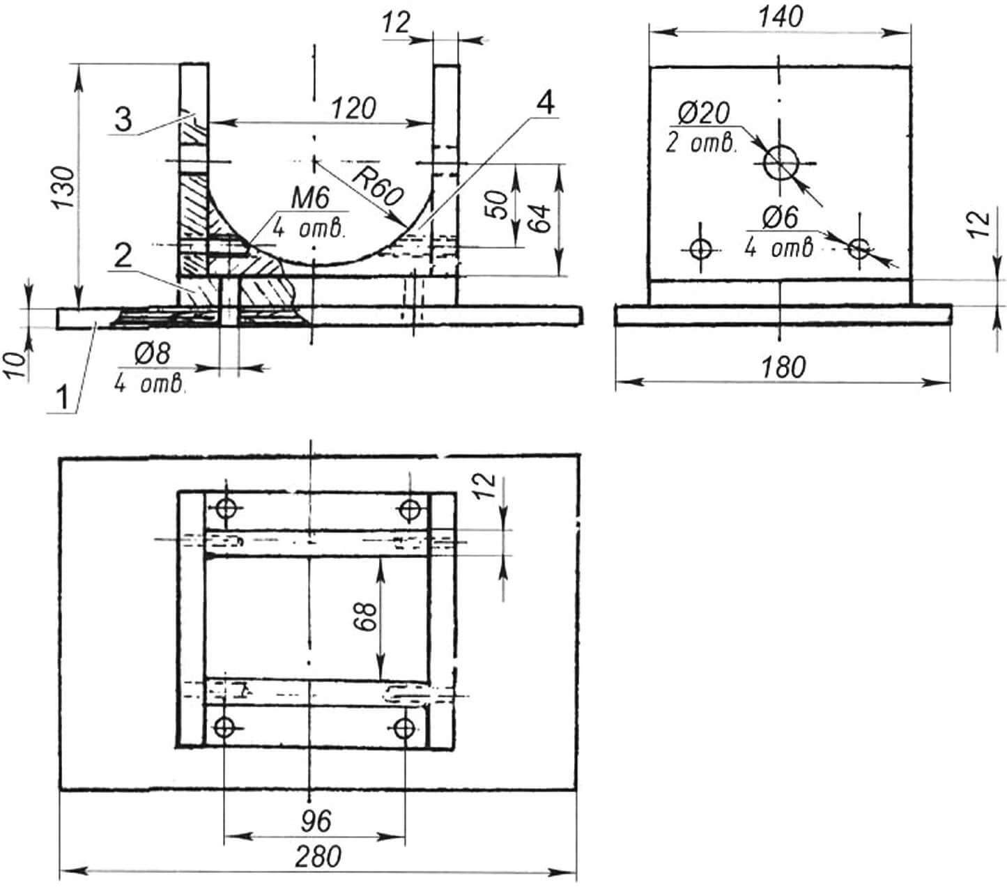
1 — underlay support (epoxy plywood s10); 2 — base (duralumin, sheet s12); 3 – cheek (duralumin, sheet S12, 2 pcs.); 4 – lodge (duralumin, sheet S12, 2 pcs.)
The mast is made of a duralumin pipe with an outer diameter of 120 mm (wall thickness 3 mm) 8 m long. To the mast, almost along its entire length (7.5 m), attached with shurups-puzzles-cut along a hacksaw 3 mm duralumin pipe external diameter of 20 mm (wall thickness 2 mm).
Next, the slot was unclenched with duralumin wedges to a width of 5-6 mm (according to the diameter of the secret head of the screw-samorez). Through this slot, the holes at a distance of 200 mm from one another were drilled simultaneously in the licpase and in the mast. The holes in the Likpaz were zenovy, and self-tapping screws were screwed into them. After the final fastening, the edge of the slot was dulled, and its width was restored to 3 mm.
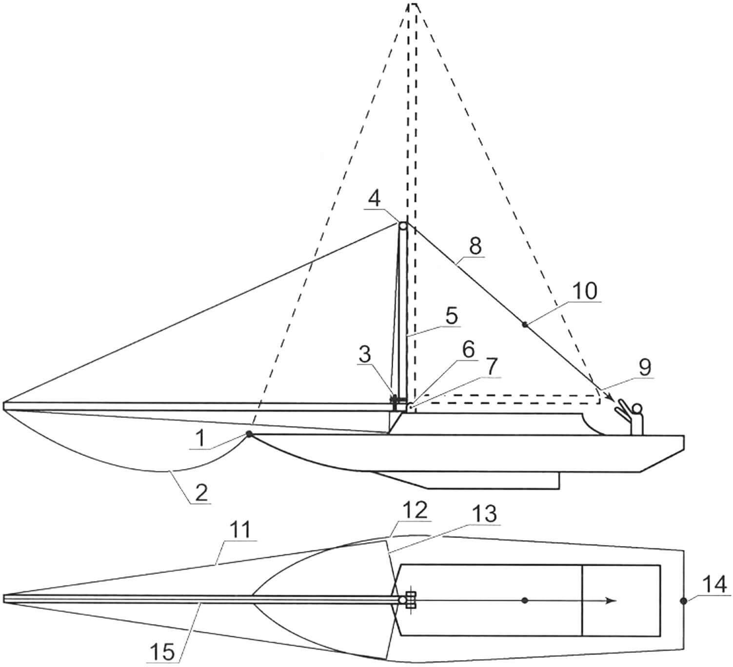
1 – the nasal place of fastening of the frying forester; 2 – praztag; 3 – hinges of geek; 4 – the rear end of the geek; 5 – geek; 6 – steps; 7 – a support bolt of the mast; 8 – Akhtsrstag; 9 – lengthening fal Akhterstag; 10 – a connecting node between the Akhterstag and the lengthening falle; 11 – on -board cable (2 pcs.); 12 – the place of fastening of the on -board bath on the deck (2 pcs.); 13 – stretching when installing a geek (2 pcs.);
14 – the place of fastening of the Akhterstag on the deck; 15 – mast
A clamp (duralumin strip, 50 mm wide and 4 mm thick) is put on the lower part of the mast (in the steps), which is pivotally suspended by an oak geek with a diameter of 80 mm and a length of 3.5 m.
Sailing weapons, consisting of a grotto and staxel – purchased, from a sports yacht type “Dragon”: the total area of the sails is 22 m 2 . The grotto is associated with the shoulder strap (duralumin bar with dimensions of 1500x60x6 mm), strengthened by epoxy glue and screws on the roof of the stern of the cutting through the substrate (strip of waterproof plywood with dimensions of 1500x30x10 mm) through the slider, moving along the entire length of the latter. Fal Giks, through the blocks between the slider and the geek, is wounded on a manual winch mounted on the bulk reproduction, which allows you to control the grotto without much effort from the cockpit. The fal of the lower cadet of the Staxel can also be started on the winch and fixed with a stopor of the stackelfusel, that is, there is the opportunity to control the stakel depending on the strength and direction of the wind.
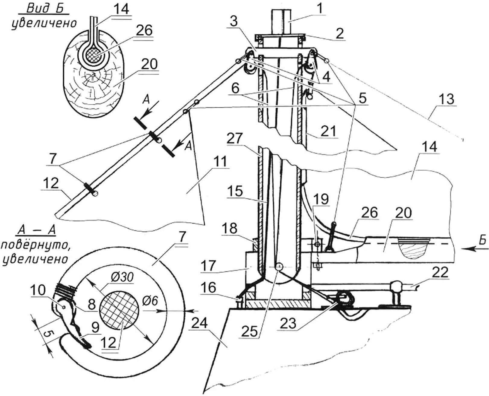
1 – running lights; 2 – mast cover (stainless steel, sheet S2); 3 – a bar for attaching the headings and a cable (stainless steel, strip 200x30x4); 4 – blocks (2 pcs.); 5 – earrings (5 pcs.); 6 – headlights (2 pcs.); 7 – rings of the leaf of the forester with the anterior cadet of the staxel (set); 8 – ring spring; 9 – latch; 10 – axis of the latch; 11 – Staxel; 12 – praztag; 13 – Akhterstag; 14 – grotto; 15 – electric cable; 16 – SR connector; 17 – steps; 18 – clamp; 19 – bolt of the hinge node of the geek; 20 – geek with liquids; 21 – licpases of the geek mast; 22 – handrail; 23 – duck; 24 – cutting; 25 – mast axis in the step; 26 – Liktros
Standing rigging and headlights are made of steel stainless ropes (cables). Around the cockpit on the deck and the wheelbarrow are shktov winches, stoppers, blocks and ducks for runners of runic touxing. In addition, two ducks for mooring are installed on both sides of Kokpit.
The mast set on the vessel is carried out in the following way.
-The mast is laid horizontally along the boat and is fixed in the steps with an axis-Bolt through the hole at its base.
– Next, the headquarters are divorced from it to the places of their attachment on the deck, to which they are hooked through talreps.
– The GIK is strengthened on the clamp at the base of the mast, installed vertically (at 90 degrees to the mast) and “stretched” with the headlights on the sides.
– Akhterstag lengthened by the phala and from the cloth through the back end of the geek is started to the stern. The tension of the Akhterstag behind the farm towards the stern of the mast is set in a vertical position. On -board baths contribute to its retention from dumping on the side when lifting. Then, the elongating fal is unheated from the Akhterstag, and its end is attached through the taleop on its seating in the stern, pulling on the forestall.
The ship is equipped with all the equipment provided for in the rules. Lighting in the middle part – due to portholes, at night – from the battery with lamps in the ceiling ceiling. The battery can be recharged from the outboard engine generator.
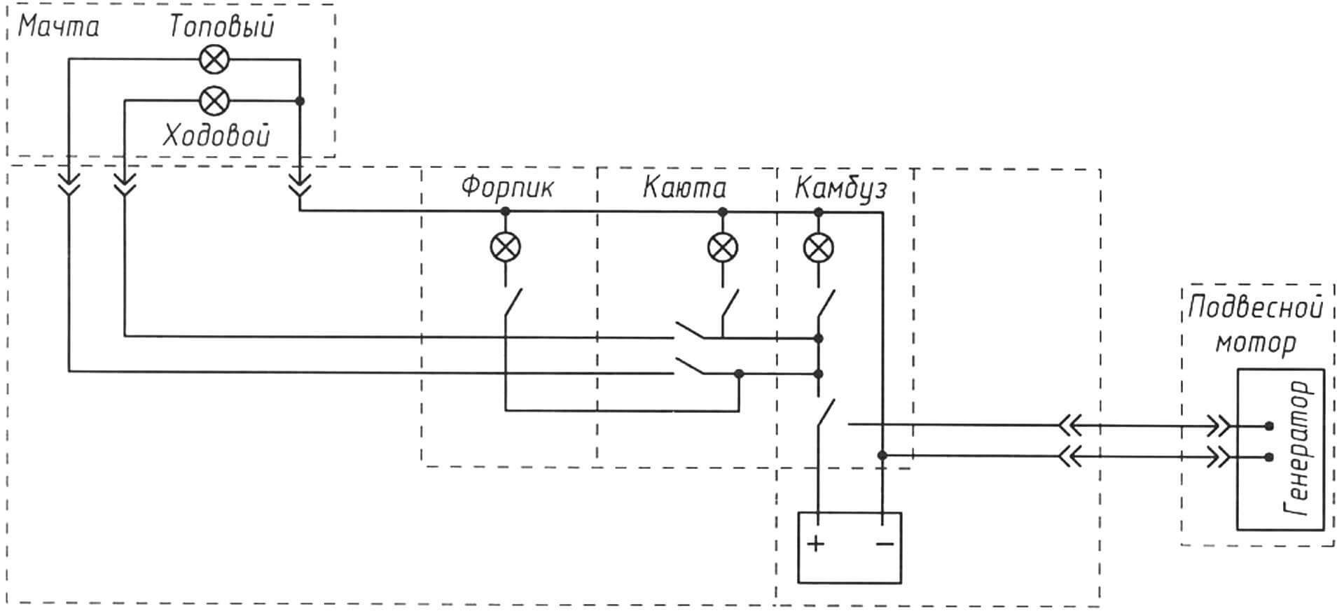
Waste lights (red, green, white) – on the cloth of the mast.
B. Sanzharovsky
Recommend to read
 ETERNAL BUCKET
Somehow, examining the parts of a worn washing machine "Siberia", drew attention to her vatoobraznye the drum of the centrifuge and realized that he could still a lot to serve, and that... Winter shelter for a tourist
Our town is located on a large "edge" of the huge West Siberian forest. The most beautiful places. Nature simply beckons to go hiking. And in the warm season, there are no problems with...
