The first homemade motorized helper appeared in our family almost 20 years ago. We built it according to V. Ilyichev’s design, published in one of the issues of the “Modelist-Konstruktor” magazine. And we were convinced how good it is to have a universal motoblock in the household, which won’t let you down in any task, whether it’s land cultivation or harvesting and transporting crops from the field.
But we weren’t satisfied with what we achieved. We decided that it would be good to add lightness in the furrow, speed, and controllability on the road to our motorized helper. Especially after familiarizing ourselves with the winch-plow and tractor-trailer systems (published, for example, in issues No. 9’81, 3’89, 4’94, 2’95, 1’97, 11’97 of the “Modelist-Konstruktor” magazine). The result of our creative thinking and experiments were various modifications of the motorized helper.
In particular, introducing two additional adjustments to the winch-plow pair gave positive results: for changing the width and depth of the cut. Now when planting potatoes, the furrow wheel goes with maximum offset toward the plowed field, and the plow covers the planted tubers with soil, automatically maintaining the required planting depth. We also found that if the soil is light and not the first year in cultivation, it’s advisable to install additional small wheels on the plow, turning the overturned plow on the return stroke into a kind of cart that, thanks to a special steel hook, freely rolls to the beginning of the next furrow.
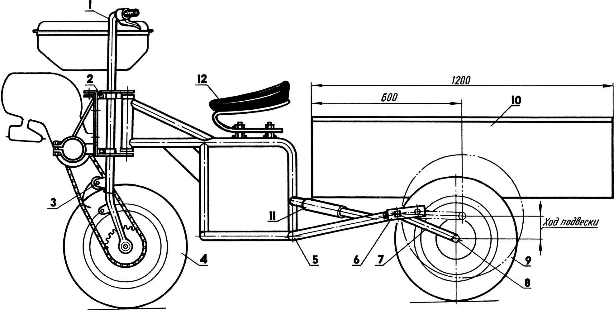
1 — Odegov’s motor tractor, modified; 2 — “soft” engine mounting unit; 3 — chain tension mechanism; 4 — front wheel, combined; 5 — dump truck frame; 6 — shackle (2 pcs.); 7 — torsion-lever suspension arm (2 pcs.); 8 — half-axle (2 pcs.); 9 — rear wheel (from “Voskhod” motorcycle, 2 pcs.); 10 — dump truck body; 11 — shock absorber (rubber hose, 4 pcs.); 12 — seat (from “Ural” motorcycle) on spring.
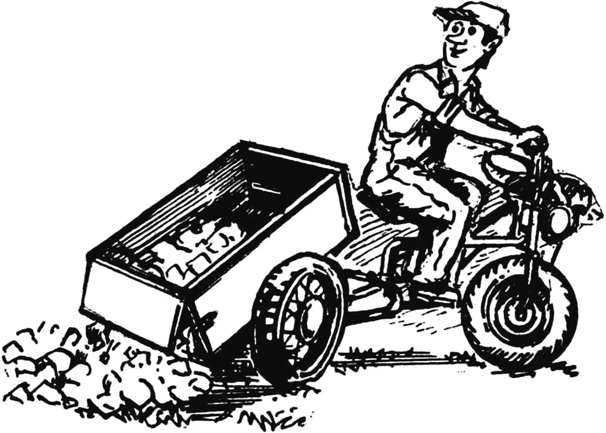
The most successful, in our opinion, were the experiments on coupling “Odegov’s motor tractor” (“Modelist-Konstruktor” No. 6’90) with a cargo cart. As a result, a design emerged that we present to the readers.
Instead of a front wheel, it has a tire from a motorized wheelchair installed. More precisely, two disks from SZA with a drum from a “Tula” motor scooter and a homemade flange with a sprocket. A special device “monitors” the chain tension, the principle of which is very similar to a so-called safety pin. It might seem like a trifle. But with them, the tractor-dump truck began to work smoothly in any situation, without chain skipping on the motor sprocket even under shock loads.
Since in this case, as in the prototype design, the engine piston performs horizontal reciprocating movements, vibrations from the power unit are transmitted to the motor tractor frame and further to the steering wheel. Therefore, a “soft” engine suspension is used. Its basis is elastic spring bushings from a “Moskvich” car, which perfectly handle vibration.
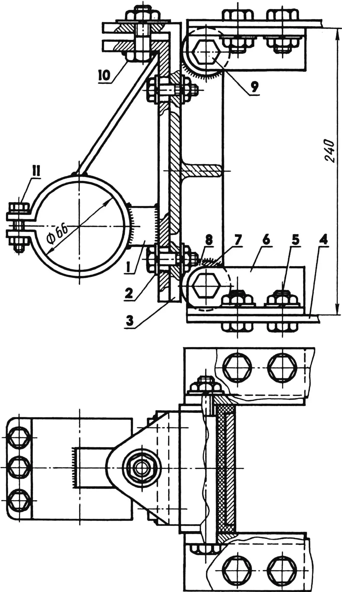
1 — slider; 2 — reinforced washer (4 pcs.); 3 — “goose neck”; 4 — Odegov motor tractor frame gusset (2 pcs.); 5 — M12 short bolt (12 pcs.); 6 — bracket (steel angle 35×35, 4 pcs.); 7 — bushing (2 pcs.); 8 — spring bushing (from “Moskvich-2140” car, 4 pcs.); 9 — M12 kingpin bolt (2 pcs.); 10 — M12 long bolt; 11 — M8 bolt (3 pcs.).
The power unit mounting bracket is made composite, with the ability to move the slider relative to the “goose neck”. The mutual arrangement of these parts is determined by a long M12 bolt screwed in from the top with a lock nut. Four short bolts passing through slots in the slider serve as guides. As a result, not only is the accuracy of power unit installation significantly facilitated, but proper tension of the roller chain transmitting torque from the driving (motor) sprocket to the driven one on the motor tractor wheel is maintained. Using two upper brackets (segments of steel angle 35×35 mm), such a composite bracket is attached to the upper gusset of the motor tractor frame, and two lower ones to the lower one.
The chain tensioner of the safety pin type is equally simple. Its actuator is made of steel wire with a diameter of 2—3 mm. Dimensions are determined on-site, and the free end of the “pin” has such a length that it freely rolls along the chain rollers (such a spring is quite sufficient for two seasons of intensive work).. But the chain tensioner washer must be substantial, representing a bent steel strip with a slot that serves as a kind of guide for the “pin” end.
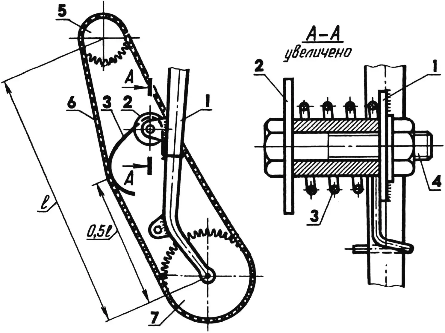
1 — steering column bracket; 2 — reinforced washer; 3 — tensioner (safety pin type); 4 — M10 bolt; 5 — driving sprocket (motor); 6 — roller chain; 7 — driven sprocket.
A motor tractor modified in this way is quite acceptable for use in a coupling with any suitable cart. And if you place the body on a trailer frame and make it tipping, combining the pivot axis with the center of symmetry, then its unloading will be mechanized. Say, “unfastened” the rear board, threw two or three shovels of cargo back—and the body will tip. It’s enough to move the dump truck forward a bit, and self-unloading will occur.
And one more, quite feasible idea: to equip such a vehicle with a shock-absorbing suspension. A slow-moving motoblock, naturally, doesn’t need it. But a transport coupling that moves not on smooth asphalt, but on potholes and ruts at speeds up to 40 km/h, such a suspension is simply necessary.
All these wishes-requirements are fully met by a design whose frame represents a symbiosis of technical solutions available in the named prototypes, with reinforcement of load-bearing elements and introduction of a torsion-lever suspension. A bushing from a segment of thick-walled steel pipe with bronze insert bearings and a kingpin bolt is used as a coupling unit.
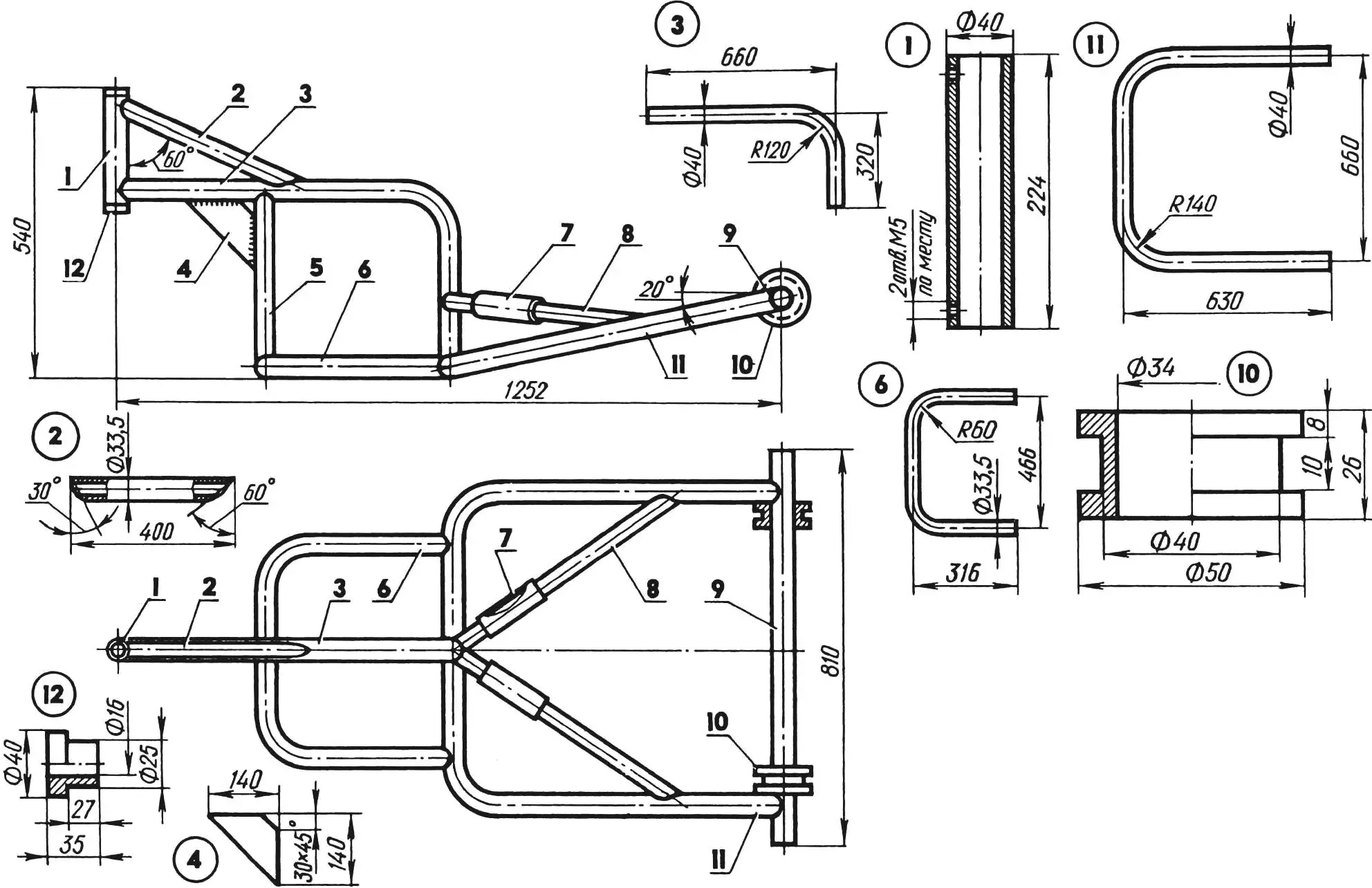
1 — kingpin bushing (with bronze insert bearings); 2 — small brace; 3 — drawbar; 4 — gusset; 5 — post; 6 — footrest; 7 — body shock absorber (rubber hose segment, 4 pcs.); 8 — large braces; 9 — cross-member bushing; 10 — body bushing, pivot (2 pcs.); 11 — subframe.
The L-shaped drawbar is reinforced with tubular braces and a gusset and connected at the bottom to the post, footrests, and subframe. Together with the cross-member bushing, it forms a strong foundation for mounting the sprung seat and pivot body, whose center of gravity falls on the middle of the cross-member bushing. The latter, being the axis of the body itself, also serves to attach the shackles of the torsion-lever suspension. And segments of rubber hose, put on the ends of the cross-member bushing and large braces, play the role of an additional shock absorber. (The lock for fixing the body in the working position is conventionally not shown.)
In the considered design, the torsions are halves of the eponymous finished product from a KamAZ truck cab suspension. One half is used without any changes, while the splined part of the second is turned into a prismatic head by reworking the cross-section to a square with a side of 24 mm. The head of each of the torsions is firmly fixed in a square socket of the corresponding shackle welded to the dump truck frame, and the cylindrical end is clamped in a split bushing of the oscillating arm.
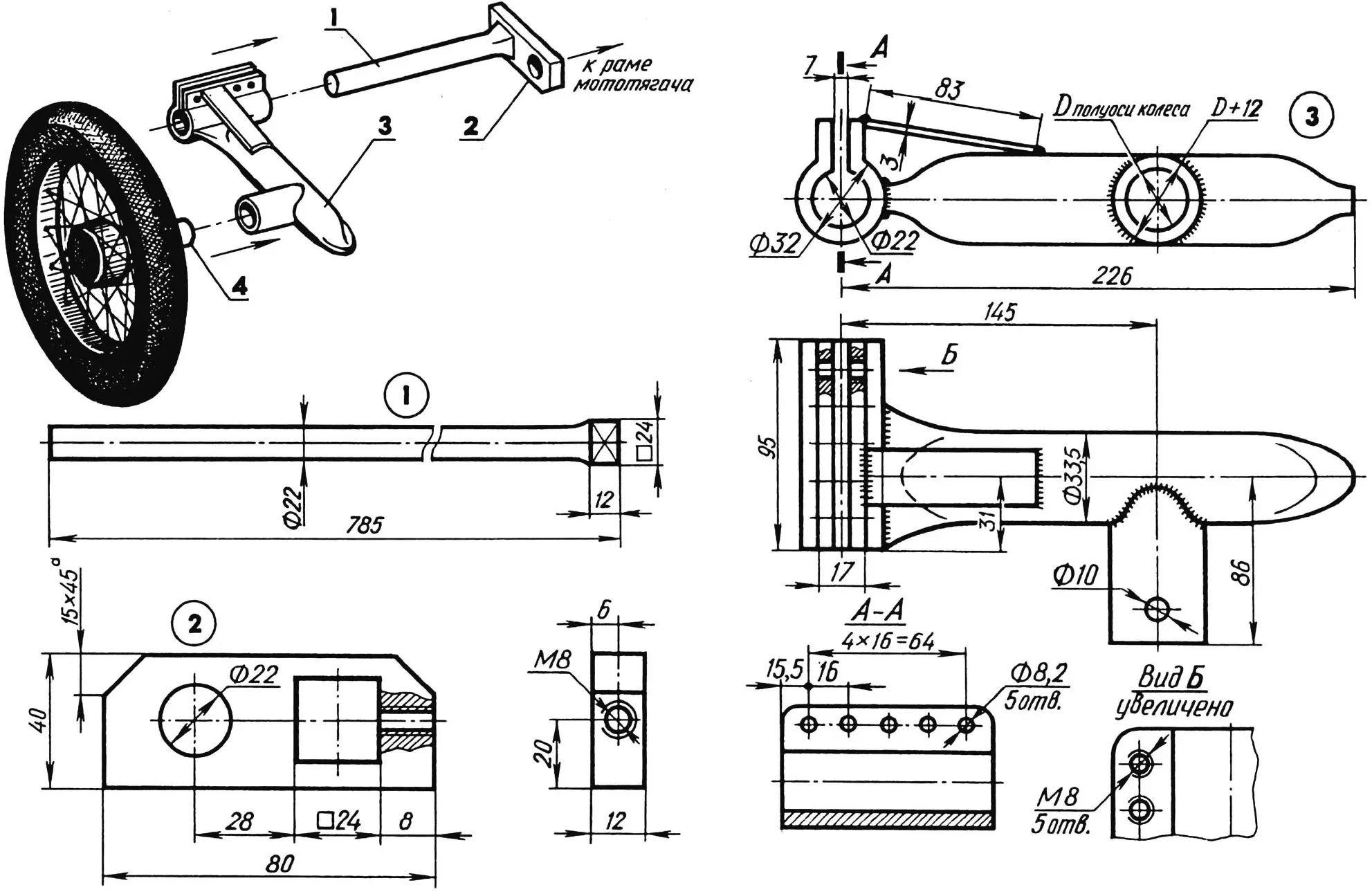
1 — torsion (from KamAZ truck, shortened by half); 2 — steel shackle; 3 — pivot arm; 4 — half-axle assembly with rear wheel.
The shackles, like both oscillating arms, are homemade. Plates measuring 80x40x12 mm from St3 grade steel served as blanks for the first. The arms are welded from steel pipes of appropriate standard sizes, and plates from the same St3 are used as braces.
Thanks to powerful split bushings, ground clearance adjustment, torsion preload, or suspension travel are ensured. The suspension elasticity is determined by the length of the oscillating arm, more precisely, the distance from the torsion center to the wheel center. Segments of rubber hose, put on the ends of the cross-member bushing and on the large braces of the frame, serve as rebound buffers.
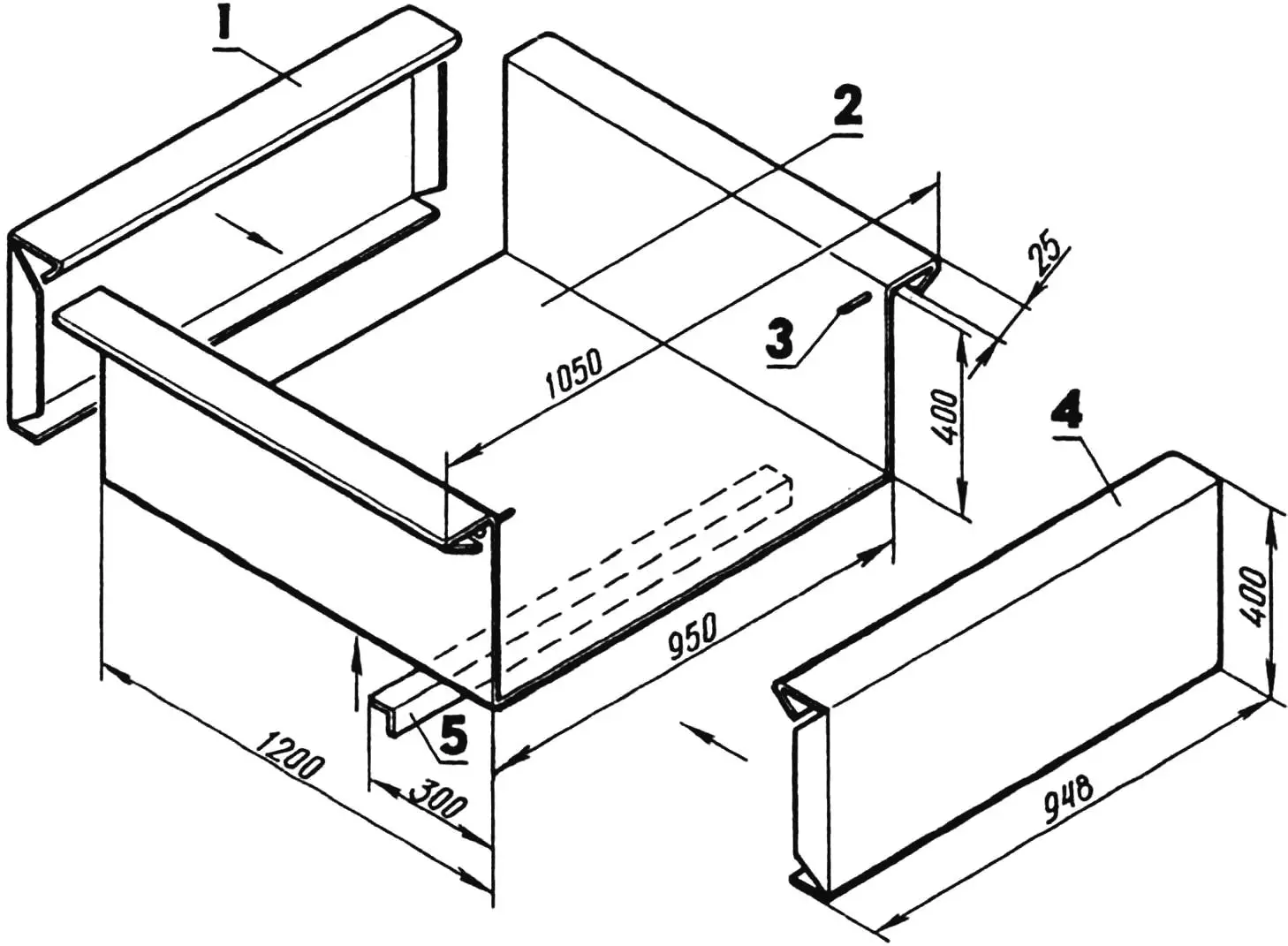
1 — front board; 2 — bottom, transitioning into side boards; 3 — rear board suspension pin (Ø10, 2 pcs.); 4 — rear board; 5 — stiffening rib (aluminum angle 45×45, L950).
Now about the body. It can be assembled from standard duralumin panels, angles, and rivets. But it’s better to use homemade bent profiles from steel sheet 1.2 mm thick. The body consists of four main parts: a bottom transitioning into sides, stiffening ribs (45×45 mm angle), front and rear boards. Moreover, the latter is removable, secured like a lid on a milk can. The upper edges of the sides are bent outward, and those of the front and rear boards inward, thus forming a frame that gives additional rigidity to the entire body. With such boards, if you blunt the sharp edges of the bends, the entire homemade agricultural machine acquires an elegant “industrial” appearance. Especially after thorough priming and final painting.
It remains to tell about the little things that significantly facilitate the operation of the motor tractor-dump truck. First, it’s an “Izhevsk” seat on a spring screwed to the frame. Second, not shown in the drawings is a protective-decorative elastic wrapping of footrests, steering column handles, and other parts with rubber bands cut from an old motorcycle inner tube. Moreover, you can assemble and similarly design a homemade “throttle” handle of the reel type for any diameter of the base tube. For this, two parts are needed: a holder from a steel strip 0.8 mm thick and a stop-holder that is attached under the front brake clamp screw. The holder is “bandaged” to the base tube with adhesive insulating tape, over which a rubber band is applied.
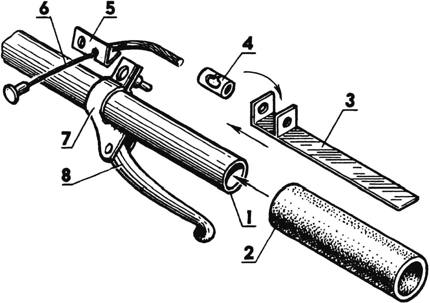
1 — handlebar; 2 — pivot handle (vinyl hose segment); 3 — holder (steel strip s1); 4 — boss; 5 — stop-holder; 6 — throttle cable; 7 — front brake lever clamp; 8 — front brake lever.
To prevent tire rotation, the wheel rim is studded, that is, equipped with peculiar protrusions-guides (but not on the side surface, but on the mounting diameter). After mounting such a wheel, the pressure in it can be reduced to a minimum. And the inner tube’s preservation is guaranteed for a long time.
The air filter is made from a plastic bottle from household chemicals. Inside it are two circles of fine mesh, between which is a stuffing of horsehair. Such a filtering element is easily removed and washed in gasoline. The filter is put on the carburetor diffuser by the neck and secured with a band clamp.
«Modelist-Konstruktor» No. 8’2000, A. NEVLENINOV
Recommend to read
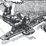 SLED-“AIRPLANE”
Needless to say that coasting on sleds is one of the most popular pastimes - a great form of active rest in winter. Is it because in different countries there are many quite different...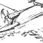 UNUSUAL GIFT
It's a letter to the editor. In it two leaves of sketches on the reverse side of which a short description and a few photos of the model. No return address, no signature of the author....
