
For a long time I have been using a long-purchased single-axle hand utility cart (unfortunately, information about the manufacturer has not survived). But, as I recall, the cart’s passport listed the following data: load capacity — 25 kg, mass — 6.5 kg. The cart is made, as they say, conscientiously; the design is reliable, it is very easy to switch from the transport position to the working one, and it happens that I carry loads of up to 50 kg on it — that is, twice the passport figure. It is now clear that the cart’s manufacturer played it safe and gave an understated load-capacity figure, because the cart’s capabilities are much greater. The designer could have indicated the real load-capacity value, but that would have required strength testing of the cart. It should be noted that hand carts were not made under the motto “Faster, higher, farther!”, so the important figure was given intuitively, “by eye”. Experience operating the cart led me to the idea that a load capacity of 25 kg can be provided by a design with smaller dimensions and lower metal consumption. Accordingly, the product should become inexpensive, have a low mass, and take up very little space when folded. From the parameters given in the GOST standard (“Solid rubber tires”), it was easy to determine that an allowable load of 25 kg is sustained by a very small disc-type tire only 40…60 mm in diameter and with a rim width of 20 mm. The design finally “matured” in my head after reading a note in the magazine “Modelist-Konstruktor” No. 11 for 1989, “Triangle cart”, about using a cane to control a hand cart. As a result, I managed to solve the engineering problem, adding yet another product to the range of hand carts.
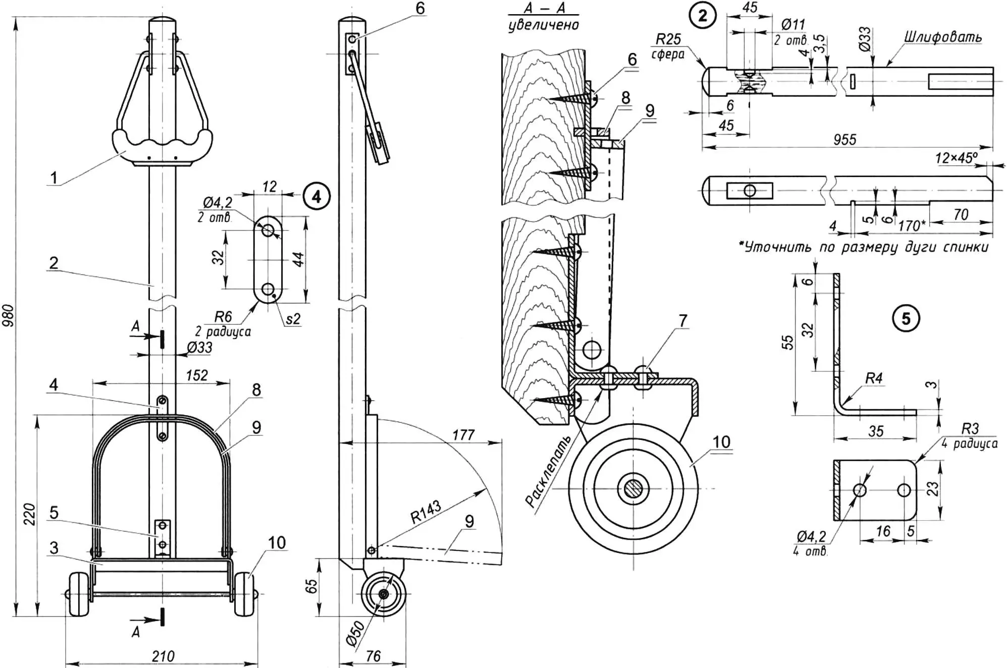
1 — handle; 2 — drawbar (shovel shaft Ø40); 3 — chassis; 4 — clamp (steel, sheet s2); 5 — angle bracket (steel, sheet s3); 6 — screw (Ø4×16, 5 pcs.); 7 — steel rivet (Ø4×10, 2 pcs.); 8 — backrest arch; 9 — load arch; 10 — wheel pair with axle
I have been using the designed and built cart for four years already. It moves very well on asphalt pavement, and a bit worse on a compacted dirt road.
In the initial version I made solid wheels 50 mm in diameter from aluminum alloy D16T, and a drawback showed up at once — when rolling, the wheels vibrated and made a lot of noise. Therefore another wheel version was made, a composite one of two parts: a hub of polyethylene and a tire of rubber with increased hardness. Because the greater the hardness of the tire, the greater its load capacity and the lower the rolling resistance of the wheel. The rubber hardness should be 60…75 Shore units.
Now in more detail about the product, which I called the “Tiny cart” because of its small size and a mass of only 1.1 kg.
The single-axle hand cart (Fig. 1) consists of handle 1 with drawbar 2, which is attached to chassis 3 by plate 4 and angle piece 5. As a blank for the drawbar I used a knot-free shovel shaft. I reduced the shaft diameter to 33 mm by planing it with a plane and then carefully sanding it with abrasive paper.
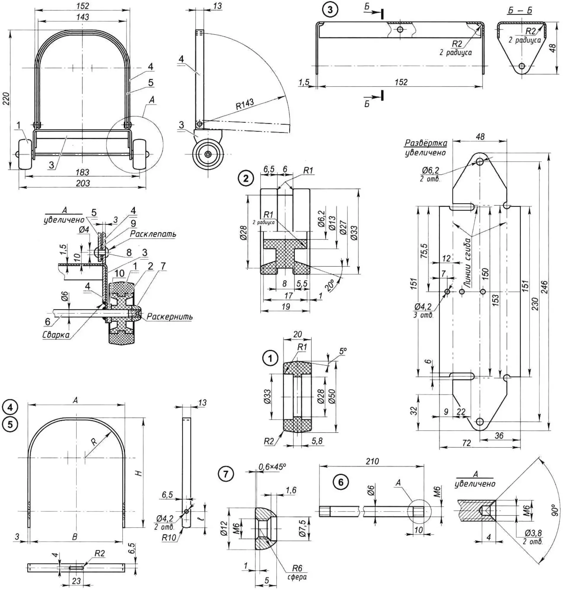
1 — tire (rubber 1F-I-MBS, sheet s20, 2 pcs.); 2 — hub (polyethylene, 2 pcs.); 3 — frame (steel, sheet s1.5); 4 — backrest arch (steel, sheet s3); 5 — load arch (steel, sheet s3); 6 — axle (steel, round bar 6); 7 — wheel fastening on the axle (special nut M6, 2 pcs.); 8 — arch joint hinge (steel rivet Ø4×10, 2 pcs.); 9 — spacer washer (2 pcs.); 10 — antifriction washer (polyethylene, sheet s5.5, 2 pcs.)
Dimensions in mm
| Designation | Developed length | A | B | H | L | R |
|---|---|---|---|---|---|---|
| 4 | 455-2 | 152 | 146 | 172 | 26 | 40 |
| 5 | 402-2 | 143 | 137 | 148 | 6.5 | 35 |
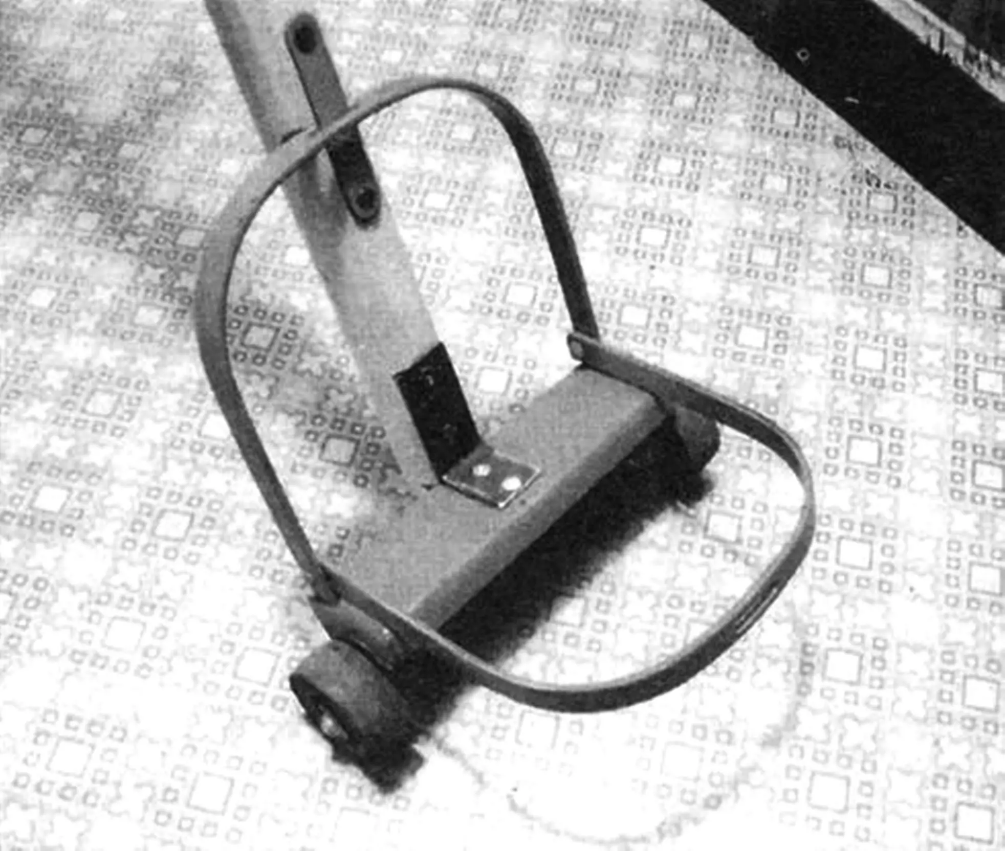
The chassis (Fig. 2) consists of frame 3, two wheels with tires, axle 6, and two arches nested one inside the other: one, the outer one, is backrest 4, and the other arch is load platform 5 (when folded for carrying, it tucks into the opening of the backrest). Frame 3 is made of 1.5 mm thick steel sheet. While making the cart, I came across an advertisement for a company’s sheet-metal laser-cutting service. To my order the company cut the blanks of the frame and the two arches on a laser machine and bent them according to the drawing.
To make the handle (Fig. 3) I bought a polyethylene grip 4 in a store, intended for fitting onto bag straps so that they do not “cut” into the hands when carrying heavy loads. Bow 1 is placed in the slot of this purchased grip and fixed there with wooden plug 3 using two cotter pins 6 made from nails (the nail ends that protrude from the grip body must be bent over and sunk in). After fitting cover plates 2 onto the bow ends and tightening locknuts 5, the ends are riveted over. The handle is fastened to the drawbar with four screws using the cover plates.
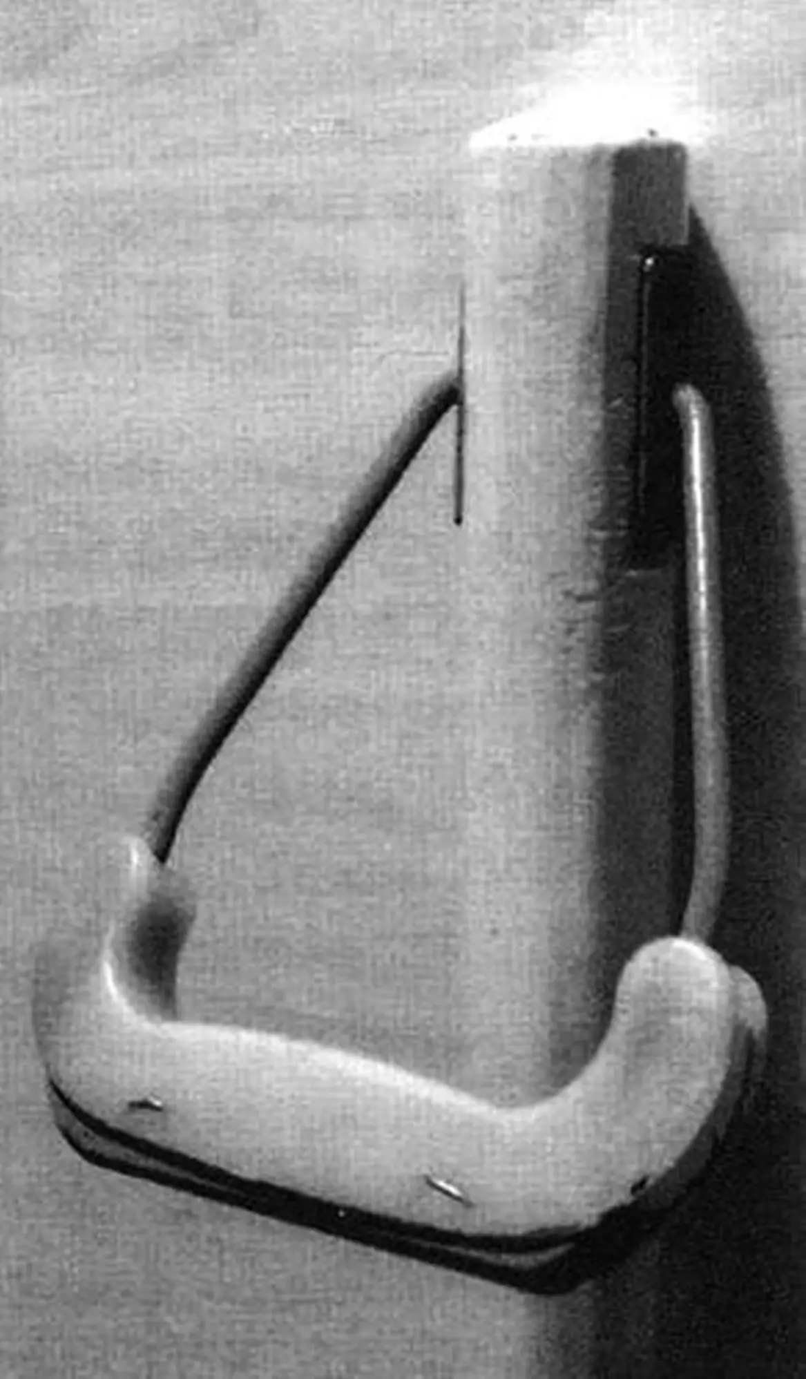
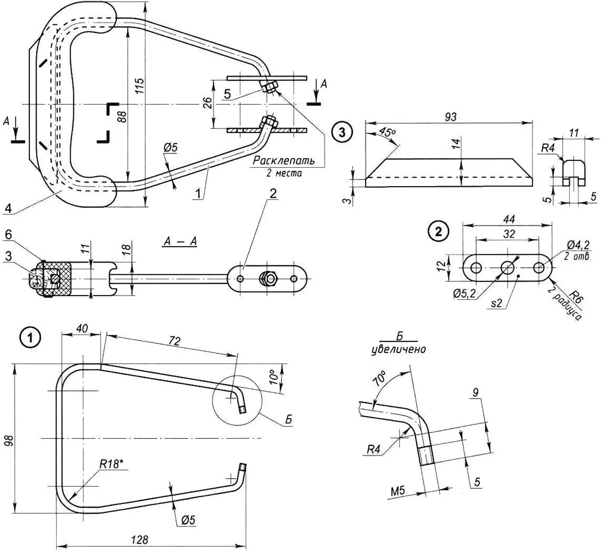
1 — bow (steel wire Ø5); 2 — cover plate (steel sheet s2, 2 pcs.); 3 — plug (hardwood); 4 — grip (purchased part); 5 — stop (M5 nut with bevel washer, 2 pcs.); 6 — cotter pin (nail Ø1.2×25, 2 pcs.)
*Adjust to the radius of the purchased grip
For transport, the load on the cart should preferably be placed with its long side vertical along the drawbar. If the load has rigid walls (for example, a suitcase), it must be tied to the cart. When using a bag with semi-rigid sides I do not even tie it. The bag holds itself under the weight of the load: first, by the narrow side edges of the load arch — its bottom is slightly crushed and hangs over the sides of the platform; second, by the drawbar, which also slightly crushes the side wall, and this prevents the bag from slipping off.
References used:
1. A.G. Lysyakov. Auxiliary equipment for moving loads. Moscow: Mashinostroenie, 1989.
2. Magazine “Modelist-Konstruktor” (Tips from around the world): No. 9/1986 “Suitcase trailer”, No. 11/1989 “Triangle cart”, No. 2/1990 “Without a porter...”
3. GOST 5883-89. Solid rubber tires. Specifications.
“Modelist-Konstruktor” No. 4’2011, Yu. ABANNIKOV
Recommend to read
 …AND GLASS CUTTER — LIKE NEW
Zatulovskaya glass cutter with carbide rollers can return to its former performance. Usually, the cutting edges of the rotating rollers wear unevenly. If they are fixed in position, in... RC ROCKET PLANE
We introduced readers interested in a new flying class, with the design of the world Cup winner F. Barnes. Judging by editorial mail, the model has attracted the attention of athletes....
