
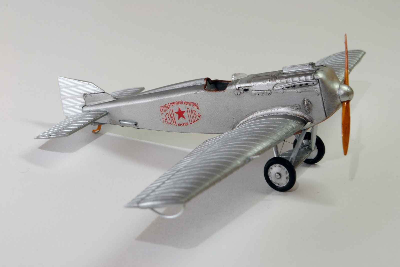
 FIGHTER AND-1. Scale model 1:33.
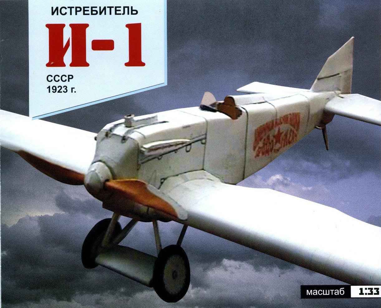
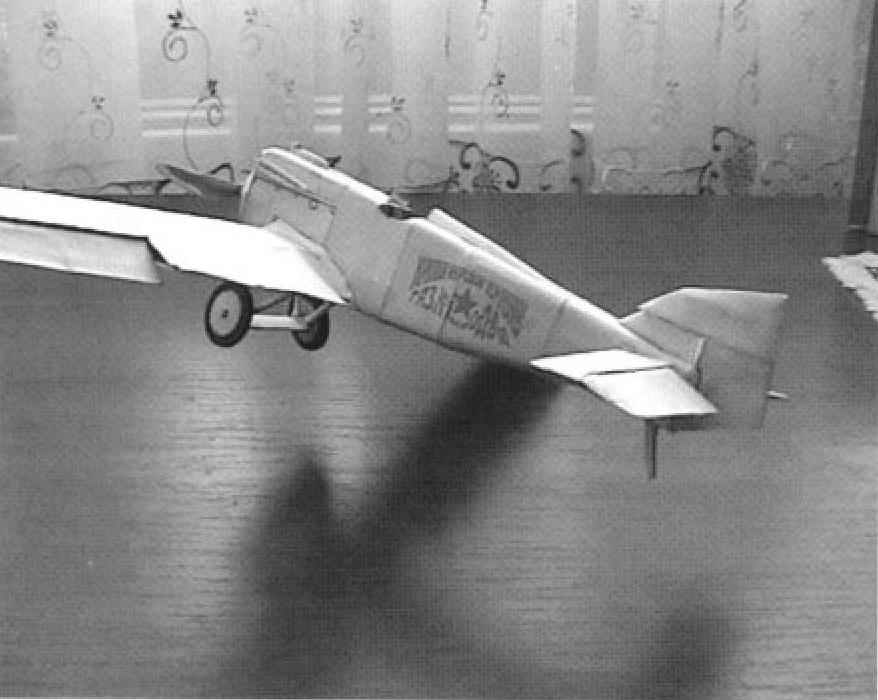
I-1(Il-400Б) first Soviet fighter monoplane.
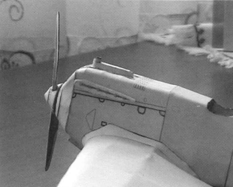
The first Soviet fighters were developed under the leadership of N. Polikarpov (in collaboration with I. M. Kostkina) and D. P. Grigorovich under the one in the early 20-ies of the licensed motor water cooling “liberty” with a capacity of 400 HP
The name of the motor is reflected in the designation of the first fighter of N. N. Polikarpov IL-400 (istrebitel with liberty в400 L. E.), which started in March 1923
The vast majority of foreign fighters of that time had a biplane scheme N. N. Designed Polikarpov IL-400 according to the scheme of freely carrying monoplane. Trapezoidal wing, it had no struts or other supporting elements. The entire power structure was on the inside of the wing.
The main advantage of IL-400 compared to other fighters was its aerodynamic design. For much less than the biplane, the drag it is possible to obtain the best flight performances, first and foremost, speed. According to calculations it was 260 km/h is very high at that time
By the summer of 1923 the aircraft was built. July 18, 1924, K. K. Artseulov first flew on the IL-4006, then to the connected test pilots A. I. Zhukov and A. Kato, who in October 1924, the completed factory testing. The plane carried nearly all aerobatic maneuvers, including deep bends, spiral, loop, corkscrew. The pilots noted that the aircraft performs aerobatics clean and very controllable. On state tests IL-4006 confirmed its high characteristics surpassing the requirements of the air force. At the same time there were some defects. In particular, it was noted that to control the airplane while performing aerobatics the pilot requires too much physical effort; presented also a requirement to increase capacity, facilitate approach to the motor when the inspection, etc. it was thought that after completing these requirements, the aircraft can take on Board. Ordered 33 aircraft.
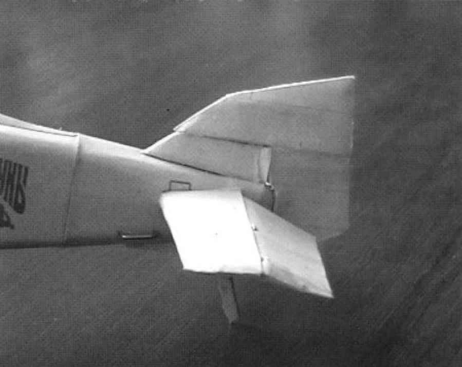
 Production aircraft began to be issued in early 1926, They were given the name I1-M5 (the first fighter with a motor M5). They differed from IL-4006 form of feathers and wood construction. The latter was due to the need to accelerate and simplify the development And-1 in the series, and also the acute scarcity of kolchougaluminium in those years. Static testing showed the lack of strength of wings in the test report of serial And-1 at the air force Institute in 1927 the results of tests of serial fighter-1 has been recognized as dangerous to fly and not adopted. It was built only 18 aircraft I-1.
Thus, the first popytka create istrebitelya svobodnensky monoplane ehbm was unsuccessful. To some extent this was caused by and is clearly insufficient knowledge, both theoretically and experimentally a number of issues related to sustainability and a corkscrew. However, experience from construction and testing I-1 proved to be very valuable.
First, was the experimental material necessary for the analysis of phenomena; secondly, the experience gained helped to accelerate and deepen research on some important issues, aviation science; third, the experience of creating And-1 showed that at the design stage cannot be ignored aerodynamic testing of models and the need to strength test.
Of course, in the mid 20-ies of the fighter And-1, made by the scheme of freely carrying monoplane, did not possess noticeable advantages over biplanes. It still could not legitimately be called high-speed monoplane. But as if he anticipated the main trends of development of aircraft of this class. After 10-12 years this has become the dominant fighter aircraft
The designers of the aircraft And-1 made a very important thing in the world They first created a fighter, a cantilever monoplane. It was an achievement of great importance. They applied the scheme in ten years, when the retractable landing gear in flight, became the dominant fighter in the world.
The other fighter, also referred to as I-1, was developed under the leadership of D. P. Grigorovich and went to trial in October 1923 under the scheme it was a single-strut biplane of wooden construction. The upper and lower wings have the same shape in plan. The aircraft was tested at the Moscow airport and has not shown the expected data speed was equal to only 230 km/h and rate of climb were unsatisfactory: did not manage to establish cooling of the engine had other disadvantages. In short, it required thorough debugging of the aircraft.
 Assembly instructions
1. Before beginning Assembly, carefully read the installation drawings and diagrams.
2. Use paper and cardboard in accordance with the markings.
3. Parts of the skeleton should be cut along the bounding black lines, trim and color details – the border line color
4. When gluing the frames are advised to spend at the ends of the part with a blunt knife or sandpaper
5 Details that need to curl into a roll or cylinder, for better twisting route through the edge (corner) of the table
6. All the white ends of the parts (paneling glue) you need to paint the markers of the corresponding color.
7. For the best bending parts bend lines, slide a blunt knife on the back side of a part bend line.
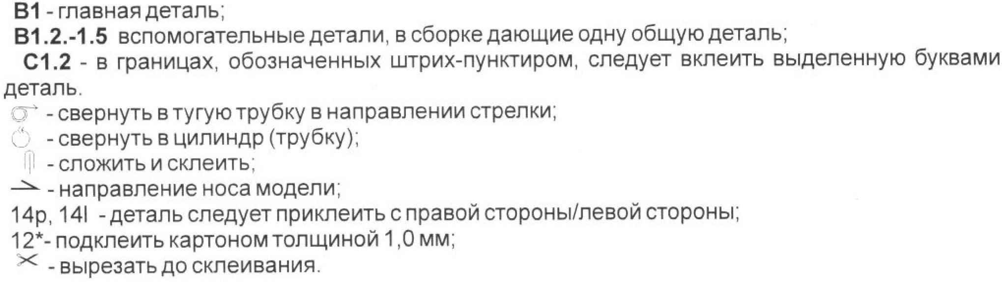
8. When assembling, consider the following notation: V1 – the main part;
B1.2.-1.5 accessories in the Assembly, giving one common item; C1.2 – within the boundaries indicated by the two-dotted, you should to paste the selected letters detail
The Assembly model is split into several stages:
1. Gluing the skeleton of the model – the nose, middle, tail,
2. Assembly of pilot seat, belts, controls.
3. Sticker covering.
4. Gluing the skeleton of the load-bearing surfaces – wings, elevators and directions. 5 Pasting plating of bearing surfaces.
6. Gluing of additional parts.
ASSEMBLY MODEL
1. Mounting of the skeleton of the model (Fig.1-3).
The skeleton of the nose of the model consists of the following parts – A-A8 When cutting ensure that not to go beyond the details indicated by the solid line. Details pasted on a cardboard of 1 mm, after which the slit Det.And individual Children.A1-A8. Please note that the details of the A7 there are extra pads covers for machine guns. These items should be pasted after pasting Det 7 And Det.. Details A1, AL-A5 should whittle away from dotted lines to solid lines. Side edge {Det Al-Ap) affixed to the structure in the last turn.
For gluing the middle part of the skeleton serve as parts – B1-B5. When gluing the middle part You should observe the following procedure for gluing: first glued to the subfloor (Det.In, B5); then on the resulting design, You should stick forming the frames (Det.B2-OT). Then insert floor itself (Det.B5.a). The first and last frames (ДетВ1, B1 .a, B1b, B4) is placed last.
The tail part consists of the following parts, 01, SR S1-S5. First, in the slot Children.With individual Children.C1-5, and then insert the side ribs CI, CP.
 2. Assembly equipment of the pilot.
Cut out the pattern dashboard (Det.B2.1., V. 2.and B2.b). The dashboard may be collected in a simplified version (used item B2.1) and the complex {uses parts V. 2.and B2.b). Complex option between parts V. 2.and B2.b is pasted a piece of transparent film to simulate the glass of the instrument panel. Foot controls consist of the following components: the pedal itself (Det.P1), side walls (Det.RI, P1.2), the main axis (Det.P1.3), the limiter (Det.P1.4), the base of the pedal (Det.R1-3). From the beginning, glue the pedals. The side walls must be folded in half, glued and then cut. After You glued the pedals, You need to glue the base of the pedal. Cut rack (det. R1), glue it to the square for a better flexure of the walls, draw on the black lines with a blunt knife. Next twist the tube Det. R2 and stick on top of Det. RZ. Now glue each side right and left pedal Assembly. For mounting the pilot’s seat first, cut out the seat and glue the colored side on the inside Attach the seat belts. Thereafter, on outer side of seat attach, respectively, the side walls of the pilot’s seat (Det.S1.1 S1.2). For fastening of the seat can be cut out of the pattern stands the pilot’s seat (Det.S3.1), and it is possible instead of patterns to use pieces of toothpicks of appropriate length,
3. Sticker covering the skeleton of the model.
Sticker skin begins with lines of gluing two frames (A8, B1). First we glue the trim and gluing (Det.4) and pasted them on top of the skeleton model. Parts should be glued so that the mark on the gluing went through gluing frames A8, B1. The correctness of the gluing in the future depends on the correctness of the model Assembly and joining of all parts of the hull. Next, sheathing is glued first to the nose of the model (Det.5, 3, 2), and then to the tail of the model (Det.6, 7, 8, 9, 10, 11, 12). Please note that Det.9 before gluing it to the skeleton should cut holes in these locations.
 4. Gluing of load-bearing surfaces (Fig. 9-10).
Gluing of surfaces is simple and shown in the respective erection drawings. It is necessary only to bonding of surfaces in frames (Det.K1.4-K1.6., E1.1, 1.3, E1.5. Rn1.1-1.3, Rn2.1, (Rn2.3, Rn2.5) to make holes for the axle mounting.
Glued the skeleton of the wing is glued to the model according to Fig. 11.
The rudder is glued in the following way: cut out the parts of the skeleton of the rudder (Det.Rw1.1-Rw2.8),Det Rw1.2, Rw1.4, Rw1.1 Rw2.4 should do
the holes for the axis direction and to cut holes for installation of the respective components. First, bonded into one unit Det. Rw1.1 – Rw 1.4 and in the other block Children.2.5 Rw-Rw2.8. Details Rw2, 1, Rw2.2, Rw2,3, Rw2.4 while the bonding between them.
5. Taping sheathing bearing surfaces.
 Taping the trim of the wings is as follows: You need to cut the trim of the ailerons (Det. 15.3), in which it is necessary to cut the holes for the frames. First cut-trim the ailerons to insert the frames of the wing, then the skeleton of the Aileron (Det.E1.1-E1.5), to pass through the axle and then bend the Aileron trim and glue. Further, basically, the skeleton of the wing covers (Children,15.1). Wingtips (Det.15.2) stick last.
The order of gluing the trim rudders are just the same as pasting the skin of the wings. First, in the slot covering of the stabilizer (Det. 16P.1) threaded frames rudder, then prisoedenaus skeleton of the stabilizer (Det.Rn2.1.- Rn2.5), in holes insert axis. Then bend the trim of the stabilizer and glue it. The order of gluing the trim of the rudder: first to the case of the model glue the block details (Rw1.1 – Rw1.4, pasted over them with a skin of the rudder (Det. 13, 13.1), then the next block of the parts of the rudder (Det.2.5 Rw – Rw2.8.) glue on the covering (Det 14.1,14.1.1) and mount it to the body (Fig.12). In the hole insert the axle and glue the block of parts of Rw2.1, Rw2.2, Rw2.3, Rw2.4. Finished gluing the rudder bonding covering the tip of the rudder (Det.14.2).
Gluing stand crutch of the aircraft shown in Fig, 13, and complexity is not.
6. Gluing of additional parts
Gluing of additional parts of the complexity will not cause and shown on the relevant drawings instructions. The safety arc and the carry handles make wire 1mm and mount thus: arcs – at the junction of the gluing of the wing skin and fins, and carry handles – in the hole Det.9.
 Performance characteristics:
Modification And-1
Wing span, m -10.80
Length, m — 7,32
Height, m
Wing area, m2 20.00
Weight, kg
empty aircraft — 1112
normal takeoff— 1510
Motor type — 1 PD liberty M-5
Power, HP — 1 X 400
Maximum speed , km/h
earth — 148
on vsote — 264
Cruising speed , km/h — 198
Practical range, km — 650
The duration of the flight, h — 2.5
The maximum rate of climb, m/min — 526
Practical ceiling, m — 6750
The crew — 1
Armament: two 7.62-mm machine gun
We wish You a pleasant bonding and pleasure from the result.
The materials to build a model FIGHTER I-1 (download)
Recommend to read
 WHEN PIPE — BUTT
Capacity pipes through their joints is a matter that must face not only the professionals who build and service pipelines. Many homebrew, rural residents, gardeners-gardeners are forced... CHEVROLET TAHOE
The sale of this American car-SUV began in our country in 2008, and the first presentation of the car took place in the United States two years earlier under the motto All-new for 2007...
