This simple model, recommended for beginners, can be built both as a glider and a rubber-powered aircraft. And in our opinion, it makes sense to assemble and master it in exactly this order: start with the glider version, and then, after gaining experience in launching and adjusting, equip it with a propeller and rubber motor.
The aerodynamic layout of the aircraft is a high-wing monoplane with a high aspect ratio wing. The construction is mixed, using packing foam, plywood, linden, and pine strips.
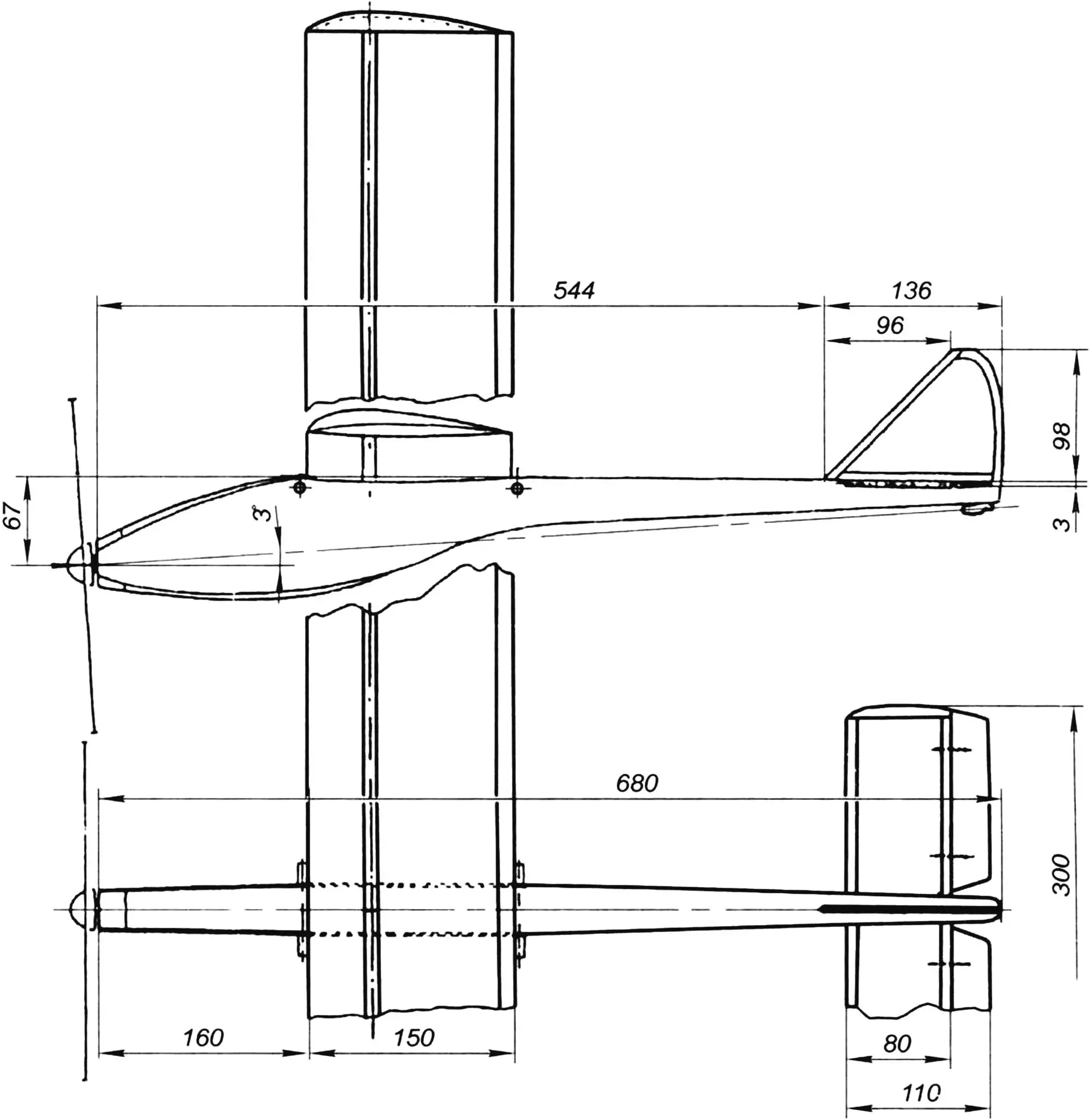
The fuselage consists of an H-shaped beam made from 1 mm plywood and filled with foam. Assembly is done using epoxy glue. At the rear, there are lugs that hold the fin and the tail hook of the rubber motor. At the front, there is a linden lug with a propeller bushing, made from a ballpoint pen shaft segment, flared on one side. A wing cradle is formed in the center of the fuselage by cutting a recess and sheathing it with 1.5 mm linden veneer. To attach the wing to the fuselage with rubber bands, 6 mm diameter beech pegs are used. The wing is fixed with a pair of 4 mm diameter pins aligned along its axis of symmetry.
The fin is a foam-filled frame: its leading edge and root rib are cut from pine strips, and the trailing edge is made of 2 mm plywood.
The horizontal tail unit is a stabilizer made of a pine frame filled with foam and equipped with attached elevator flaps. The elevators are made of linden and are connected to the stabilizer with hinges made of soft steel wire segments, allowing adjustment of the deflection angle during fine-tuning.
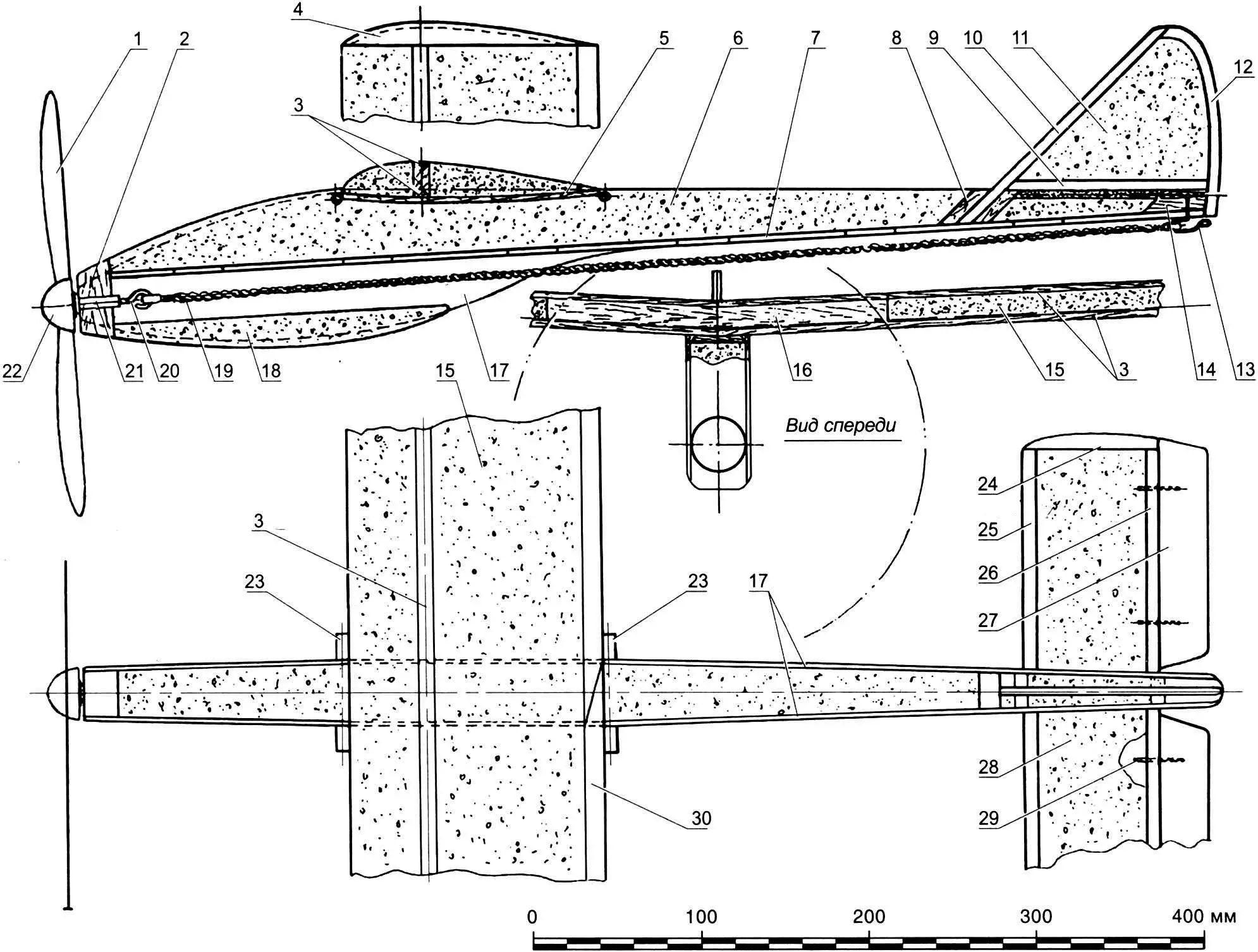
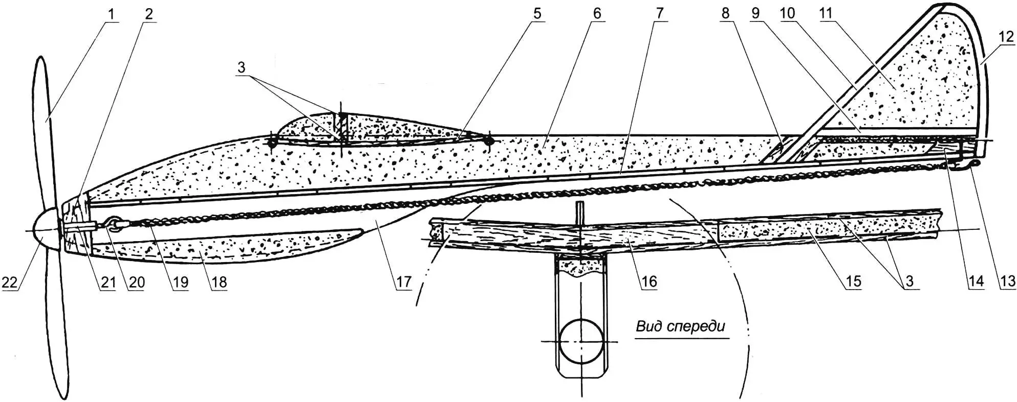
1 – propeller (linden, 30×16 mm block); 2 – nose lug (linden); 3 – spar shelves (pine, 8×8 mm strip); 4 – tip (linden, 25×18 mm block); 5 – wing cradle (linden, 1.5 mm veneer);
6 – fuselage beam filling (foam); 7 – fuselage beam partition (1 mm plywood); 8 – lug with fin socket (linden, 12×8 mm strip); 9 – fin root rib (pine, 6×3 mm strip); 10 – fin leading edge (pine, 6×3 mm strip); 11 – fin filler (foam); 12 – fin trailing edge (2 mm plywood); 13 – rubber motor hook (Ø1 mm wire); 14 – hook mounting lug (linden); 15 – wing core (foam); 16 – wing joint block (two parts, 6 mm plywood); 17 – fuselage beam sides (1 mm plywood); 18 – nose section filler (foam); 19 – rubber motor; 20 – propeller shaft (steel, Ø1.5–2 mm wire); 21 – propeller bushing; 22 – propeller cone; 23 – wing mounting pegs (beech, Ø6 mm strip); 24 – stabilizer tip (pine, 10×4 mm strip); 25 – stabilizer leading edge (pine, 10×4 mm strip); 26 – stabilizer trailing edge (pine, 8×4 mm strip); 27 – elevator (linden, 30×4 mm strip); 28 – stabilizer filler (foam); 29 – elevator hinge (wire); 30 – wing trailing edge (pine, 12×5 mm strip)
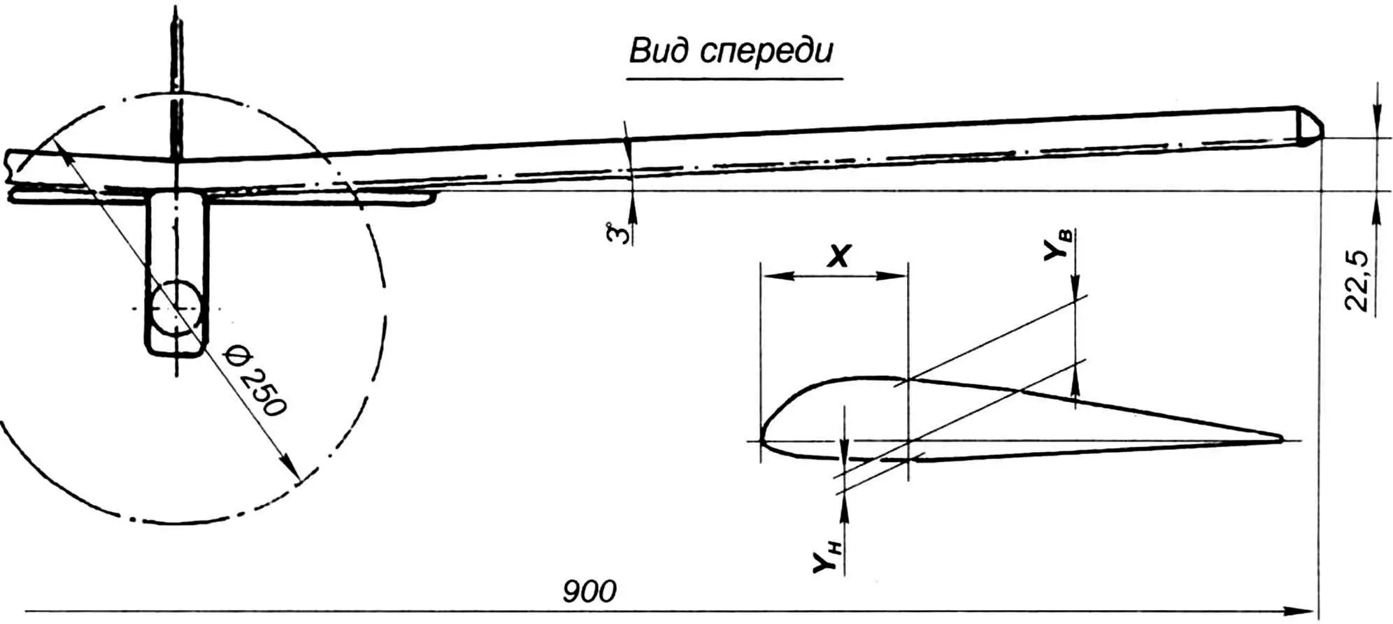
The wing also has a mixed design. Each panel is built around a foam core reinforced with two pine spar strips and a trailing edge. The core is cut from a foam block using a hot wire cutter and duraluminum templates, based on the cross-section table. The nichrome wire should be hot enough to leave a smooth, glassy surface on the foam.
The trailing edge is cut off and replaced with a pine strip glued with epoxy. Triangular grooves are cut 50 mm from the leading edge (30% chord) on the top and bottom surfaces of the wing, and triangular pine spars are glued into them with epoxy.
The prepared panels are assembled into a wing using a joint block inserted between the spar shelves, made from two plywood plates with beveled edges, glued to form dovetail slots for a rigid connection. The trailing edges of the panels are joined at an angle. Finally, two hollow linden wingtips are glued on. After sanding with progressively finer sandpaper, the foam can be primed with epoxy, sanded again, and painted with enamel.
| X | Ytop | Ybottom |
|---|---|---|
| 0.7 | 3.5 | 1.5 |
| 1.5 | 4.8 | 2.1 |
| 3.0 | 7.0 | 2.8 |
| 4.5 | 8.7 | 3.1 |
| 7.5 | 11.2 | 3.7 |
| 10.5 | 13.0 | 4.2 |
| 15.0 | 16.0 | 4.5 |
| 22.5 | 17.0 | 4.6 |
| 30.0 | 17.5 | 4.8 |
| 37.5 | 17.5 | 4.8 |
| 45.0 | 17.2 | 4.6 |
| 60.0 | 15.7 | 4.5 |
| 75.0 | 13.5 | 3.9 |
| 90.0 | 11.0 | 3.3 |
| 105.0 | 7.5 | 2.5 |
| 120.0 | 5.5 | 1.6 |
| 135.0 | 2.7 | 1.0 |
| 150.0 | 0.5 | 0.5 |
Before launching the glider, perform balancing by placing a suitable weight in the rubber motor channel. The center of gravity should be 25–30% of the mean aerodynamic chord. If the model dives steeply, bend the elevator slightly upwards; if it stalls — downwards. The flight path of a well-adjusted model should be a straight descending line. To launch with a towline, install a wire hook on the underside of the fuselage.
To convert the glider into a powered aircraft, you’ll need a propeller. You can buy a ready-made one or carve it from a linden block using the theoretical drawing and balance it. The shaft is bent from 1.5–2 mm steel wire. A brass washer is placed between the fuselage nose bushing and the propeller.
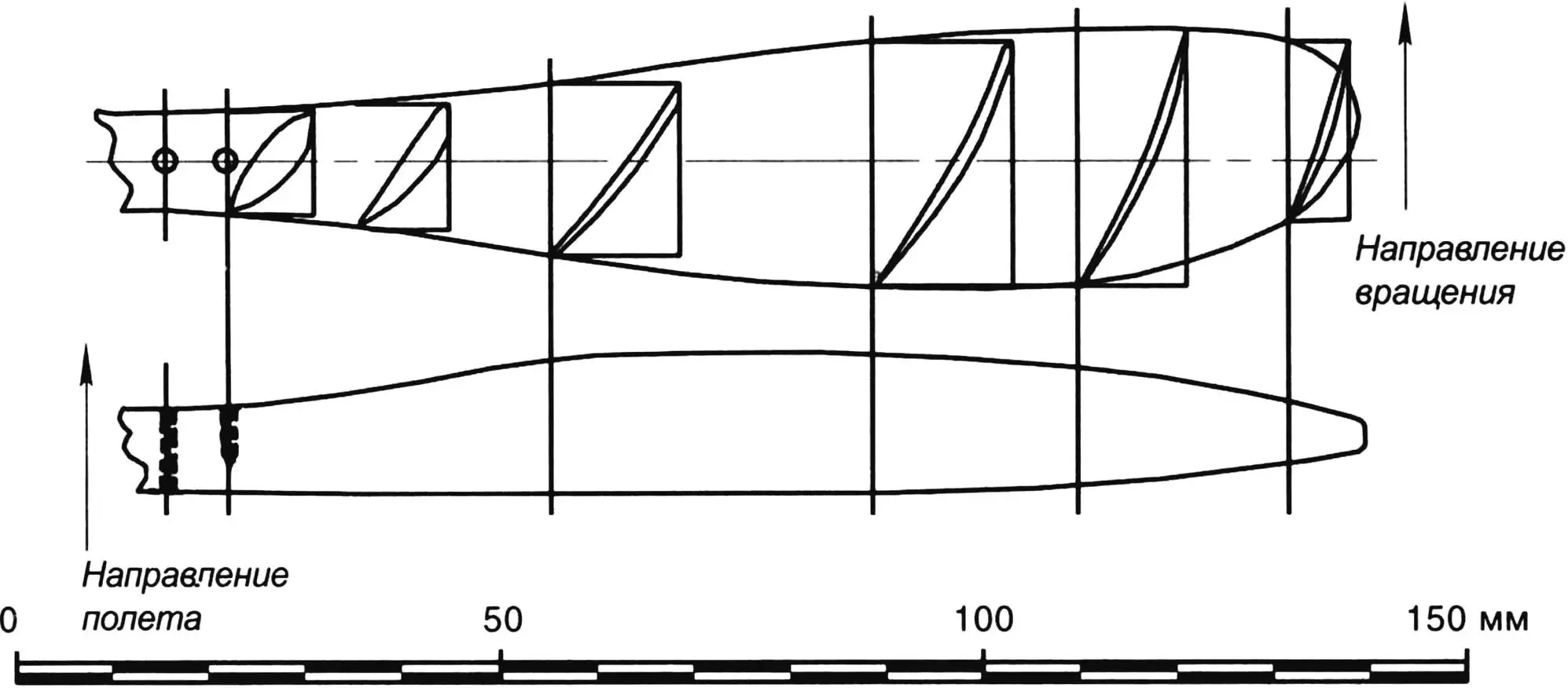
Now prepare the rubber motor. Between two nails driven into a board 650 mm apart, wind round model aircraft rubber (it should weigh about 35–40 g). Make loops at both ends of the rubber strand using strong thread. Wash the motor with soap, dry it, and lightly lubricate it with castor oil. Between flights, store it in a sealed bag.
Test launches are performed in glider mode but with the rubber motor installed. Adjust the flight path by tweaking the elevator angle. Initial powered flights use 100–150 turns of the motor. Gradually increase winding until the motor is fully wound — up to the second “knots” along its length.
Sergiy SOROKIN
Recommend to read
 ON GUARD FOR PEACE AND CAPITALISM
In October 1950, the design Bureau of the Detroit Arsenal (Detroit Arsenal Tank Plant) began designing a new tank, designed to replace the M47 medium tank. Will not be superfluous to... CORD PROTECTION
Cord electric soldering iron is typically not heat-resistant insulation. Therefore at its hit on a hot tip, perhaps a quick melt insulation and short circuit of wires. To avoid this, it...
