Unfortunately, power problems are occurring more and more frequently, and there is no guarantee that you will be spared this fate, regardless of where you live — in the city or, especially, in rural areas.
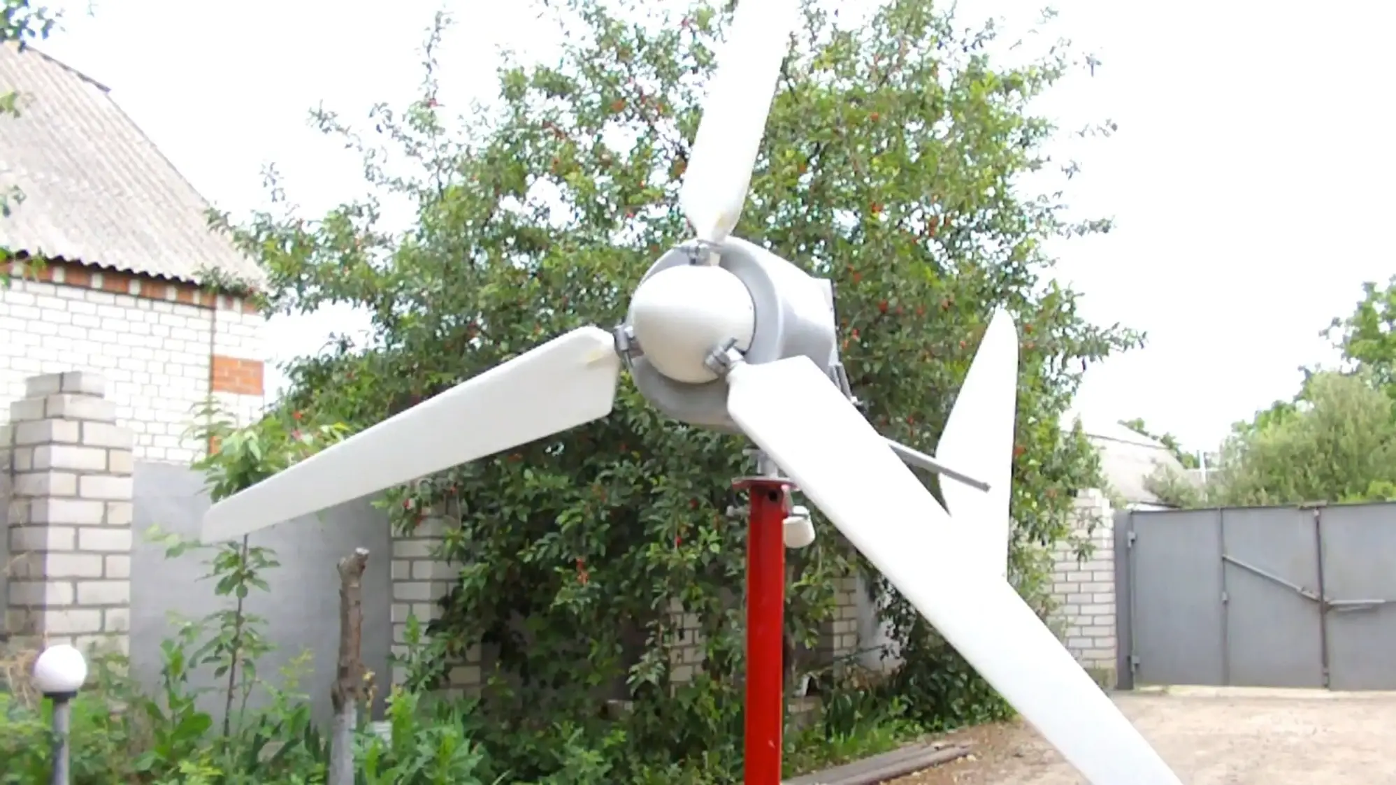
To protect yourself in case of an “emergency” situation, it’s good to purchase a diesel mini-power station, but… not everyone can afford this pleasure — the unit itself costs a lot, and you also need to “feed” it, and “oats are expensive nowadays.” Another matter is a wind generator. It can be made yourself, and then — harvest energy and use it when needed. And many thrifty owners of dachas and homestead plots do just that.
The greatest difficulty in amateur construction of a wind installation is the manufacture of an air propeller. This is related to the complex theory of its calculation. However, with sufficient accuracy for practical application, this calculation can be performed using a simplified method.
The power of the designed installation is calculated by the formula:
N=(pFV3)/2, (W),
where p = 1.25 kg/m3 — air density;
F — area swept by the air propeller, m2;
V — wind speed, average for the area per year.
Hence the area swept by the propeller:
F= 2N/pV3,
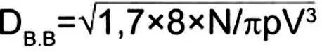
and the propeller diameter

The designed installation should be calculated for a power 1.7 times greater than the generator power, therefore
The air propeller is made from wood species that are easy to work with and not very prone to warping, such as birch or larch. The blank should be well planed and dried. Its dimensions: length — 100 mm more than the diameter of the air propeller DВВ, width — 0.09 DВВ, thickness — 0.025 DВВ.
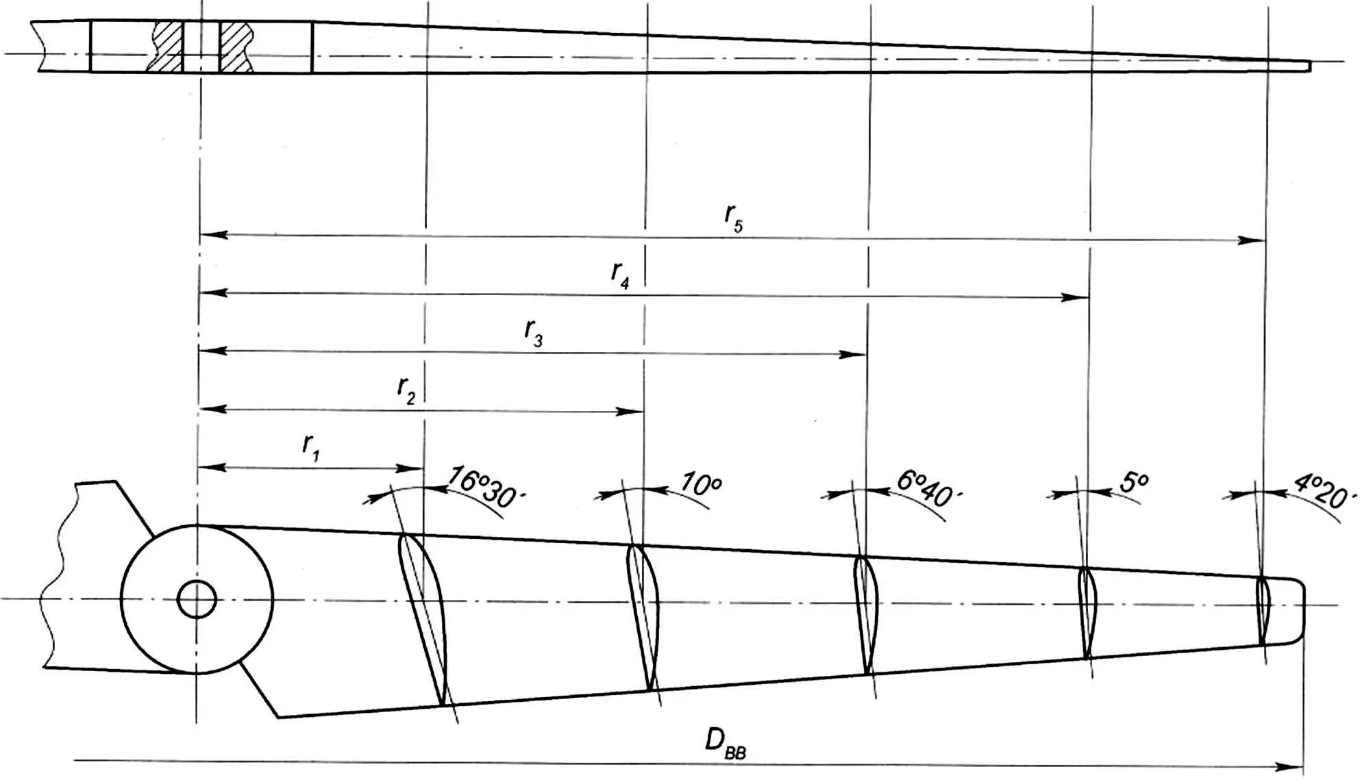
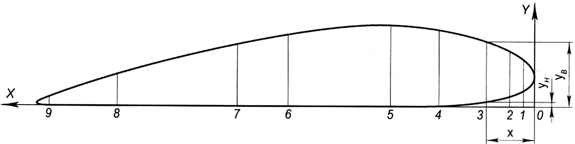
On the prepared blank, longitudinal and transverse axes are marked on both sides, and transverse lines of calculated blade sections are applied along radii r1 — r5.
Profile dimensions for an air propeller blade with a diameter of 1 m*
| Calculated section radius, r, mm | Profile angle, deg. | Profile coordinate | Coordinate x, mm | |||||||||
|---|---|---|---|---|---|---|---|---|---|---|---|---|
| 0 | 1 | 2 | 3 | 4 | 5 | 6 | 7 | 8 | 9 | |||
| 100 | 16°30′ | X | 0 | 2.1 | 4.2 | 8.3 | 16.5 | 25.0 | 41 | 57.5 | 74 | 82 |
| Yв | 6.1 | 9.0 | 10.4 | 12.0 | 14.2 | 15.0 | 13.7 | 9.83 | 4.6 | 0.5 | ||
| Yн | 6.1 | 3.4 | 2.5 | 1.7 | 0.83 | 0.32 | 0.0 | 0.0 | 0.0 | 0.0 | ||
| 200 | 10° | X | 0 | 1.84 | 3.5 | 7.1 | 14.1 | 21.2 | 35 | 49.2 | 63.3 | 71.0 |
| Yв | 5.0 | 7.5 | 8.3 | 9.7 | 11.5 | 12.2 | 11.7 | 7.92 | 3.7 | 0.41 | ||
| Yн | 5.0 | 2.8 | 2.1 | 1.3 | 0.5 | 0.22 | 0.0 | 0.0 | 0.0 | 0.0 | ||
| 300 | 6°40′ | X | 0 | 1.32 | 2.8 | 5.5 | 11.0 | 16.5 | 28 | 33.4 | 47.0 | 55.0 |
| Yв | 3.5 | 5.43 | 6.0 | 7.0 | 8.32 | 9.0 | 8.2 | 5.5 | 2.5 | 0.34 | ||
| Yн | 3.5 | 1.82 | 1.34 | 0.83 | 0.42 | 0.0 | 0.0 | 0.0 | 0.0 | 0.0 | ||
| 400 | 5° | X | 0 | 1.0 | 2.0 | 4.0 | 8.0 | 12.0 | 20.0 | 28.0 | 36 | 40.0 |
| Yв | 1.6 | 3.2 | 3.7 | 4.42 | 5.1 | 5.42 | 4.7 | 3.3 | 1.7 | 0.25 | ||
| Yн | 1.6 | 1.0 | 0.7 | 0.42 | 0.0 | 0.0 | 0.0 | 0.0 | 0.0 | 0.0 | ||
| 475 | 4°20′ | X | 0 | 0.7 | 1.4 | 2.7 | 5.4 | 8.1 | 13.5 | 19.0 | 24.3 | 27.0 |
| Yв | 1.0 | 1.74 | 2.1 | 2.5 | 2.7 | 3.0 | 2.41 | 1.7 | 0.7 | 0.2 | ||
| Yн | 1.0 | 0.54 | 0.4 | 0.13 | 0.0 | 0.0 | 0.0 | 0.0 | 0.0 | 0.0 | ||
* For a propeller of another size, multiply the table data (except for angle λ) by a coefficient equal to its diameter in meters.
The technological tooling includes a jig board and profile templates.
The jig board, like the air propeller blank, is a planed board with a length greater than half its diameter by 80 — 100 mm and is marked similarly to the blank. Holes are drilled at the intersection of the axes both in the air propeller blank and in the jig board, and a stud with a diameter of 12 — 18 mm and a length of 180 — 200 mm is fixed in the jig. Profile templates are made from 4 — 5 mm thick plywood with dimensions of 0.25×0.18 RВВ. Section profiles drawn in accordance with the table and drawing at a scale of 1:1 are glued onto the plywood blanks. After the glue dries, the profiles (shaded part) are cut out in the templates with a jigsaw, and the template is cut into two parts. Blocks with a cross-section of 30×15 mm are attached with nails to the lower one, with the help of which the profiles are installed on the jig board. In this case, the centers of the profiles must lie on one horizontal axis.
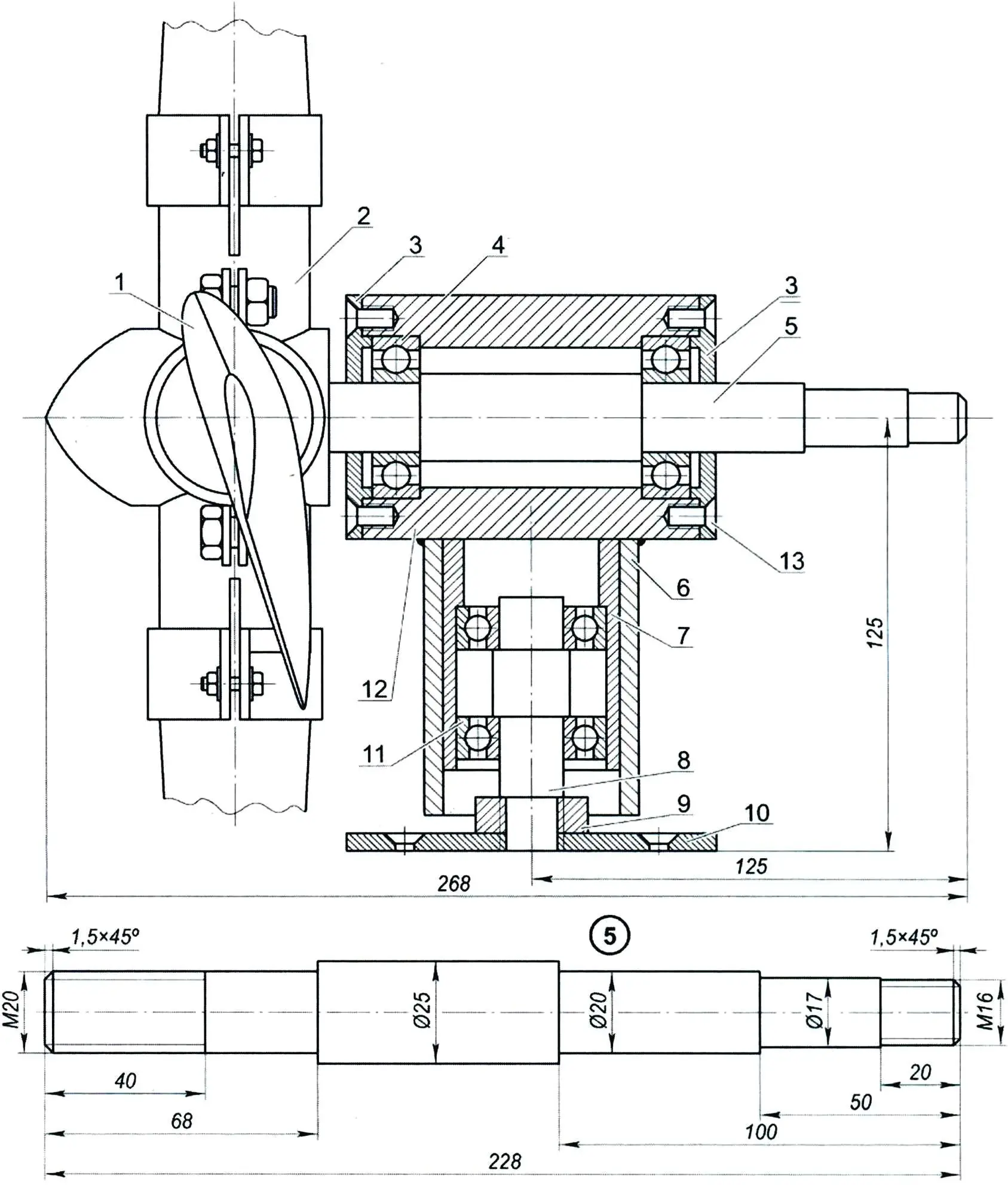
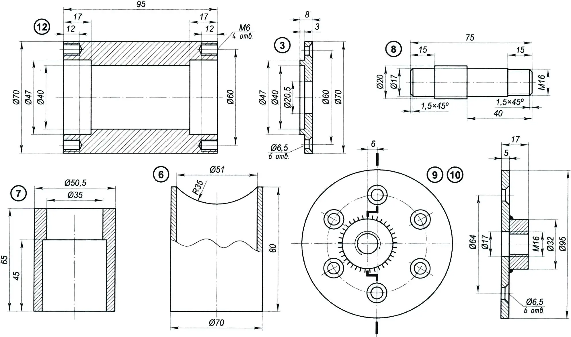
1 — air propeller blade (3 pcs.); 2 — blade mounting block; 3 — cover (2 pcs.); 4 — bearing 204 (2 pcs.); 5 — shaft; 6 — sleeve; 7 — support axis bearing housing; 8 — support axis; 9 — lock nut; 10 — support platform; 11 — bearing 203 (2 pcs.); 12 — drive shaft bearing housing; 13 — screw M6 (12 pcs.)
The propeller manufacturing process is carried out in the following sequence.
After securing the templates to the jig board, the blank is placed on the stud and lowered onto the templates, the upper edges of which are coated with paint. Then the blank is removed and wood is removed at the locations of the impressions left by the templates using a chisel 5 — 6 mm wide or a round file with coarse teeth to a depth of 4 — 5 mm. Then the blank is again placed on the studs for the next impression. This process is repeated until “markers” are obtained — continuous coloring along the profile lines. The upper part of the blade is processed similarly, with section control performed by manually touching the upper part of the templates without securing.
As in the previous case, the template edges are coated with paint.
Wood removal is performed until the lower and upper parts of the templates match.
To proceed to manufacturing the second blade, a nut is placed under the blank on the stud and secured with a lock nut, which remains so until the other two blades are manufactured. After this, the blank is rotated 180° and work begins on the second blade blank. The remaining wood between the “markers” is carefully removed with planes, processed with a file, and sanded. After this, the propeller is impregnated with linseed oil and painted several times.

1 — blade (birch or linden, 3 pcs.); 2 — clamp (strip 20×3, 3 pcs.); 3 — stud (rod Ø5, 3 pcs.); 4 — clamp fastening (bolt M8, 6 pcs.); 5 — blade clamp (tube 42×3.5, 3 pcs.); 6 — central bushing (circle Ø50); material of parts pos. 2—6—steel
The profile dimensions in calculated sections and the manufacture of three-blade propeller blades are similar. The blank for each blade is 50 — 60 mm longer than the propeller radius.
When marking, the transverse axis is positioned at a distance of 25 — 30 mm from the edge, and a hole for the stud is drilled at the intersection of the axes.
Next, a tenon is made from the side of the blade end with the hole for the stud, the diameter of which equals the blank thickness, and the length — 1.5 — 1.6 times the blank thickness.
The tenon must be made very carefully, as misalignment errors will inevitably lead to the blades being positioned in different planes.
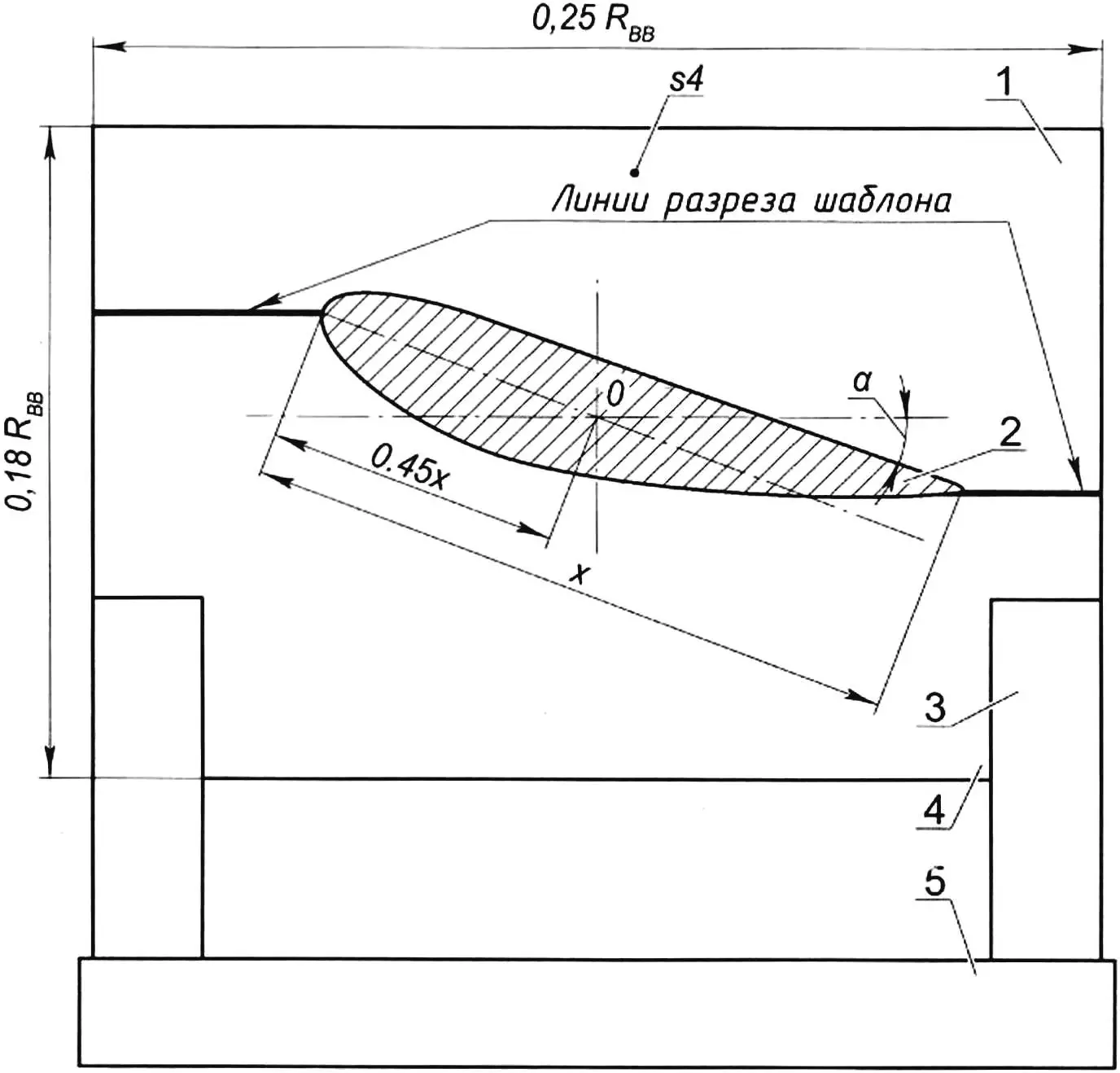
1 — upper section of template (plywood s4); 2 — profile (cut out); 3 — stand (block 15×30); 4 — lower section of template (plywood s4); 5 — jig board
When processing the air propeller blank, there may be chips or excessive wood removal. In this case, the defects are filled with putty.
The putty is prepared based on moisture-resistant glue and wood sawdust. The dried putty is carefully filed with a file and cleaned with sandpaper.
In the end part of the three-blade air propeller blade tenon, a hole with a diameter of 0.005 DВВ is drilled to a depth of 3.5 times the blank thickness. A metal stud of the corresponding diameter is inserted into this hole and filled with epoxy glue. The finished propellers must be carefully balanced.
L. KURDELYAS
Recommend to read
 ECONOMICAL AND RIGHT ON TARGET!
Perhaps the most part, even far from the sea and naval Affairs readers will agree that the word "submarine" the first thing comes to mind is the thought about German. Dark grey body,... INHABITED WING
In December 1921 on the initiative of a group Krasnotsvetov (so called in those years, military pilots of the red Army) — the staff of the research version of the Air fleet was organized...
