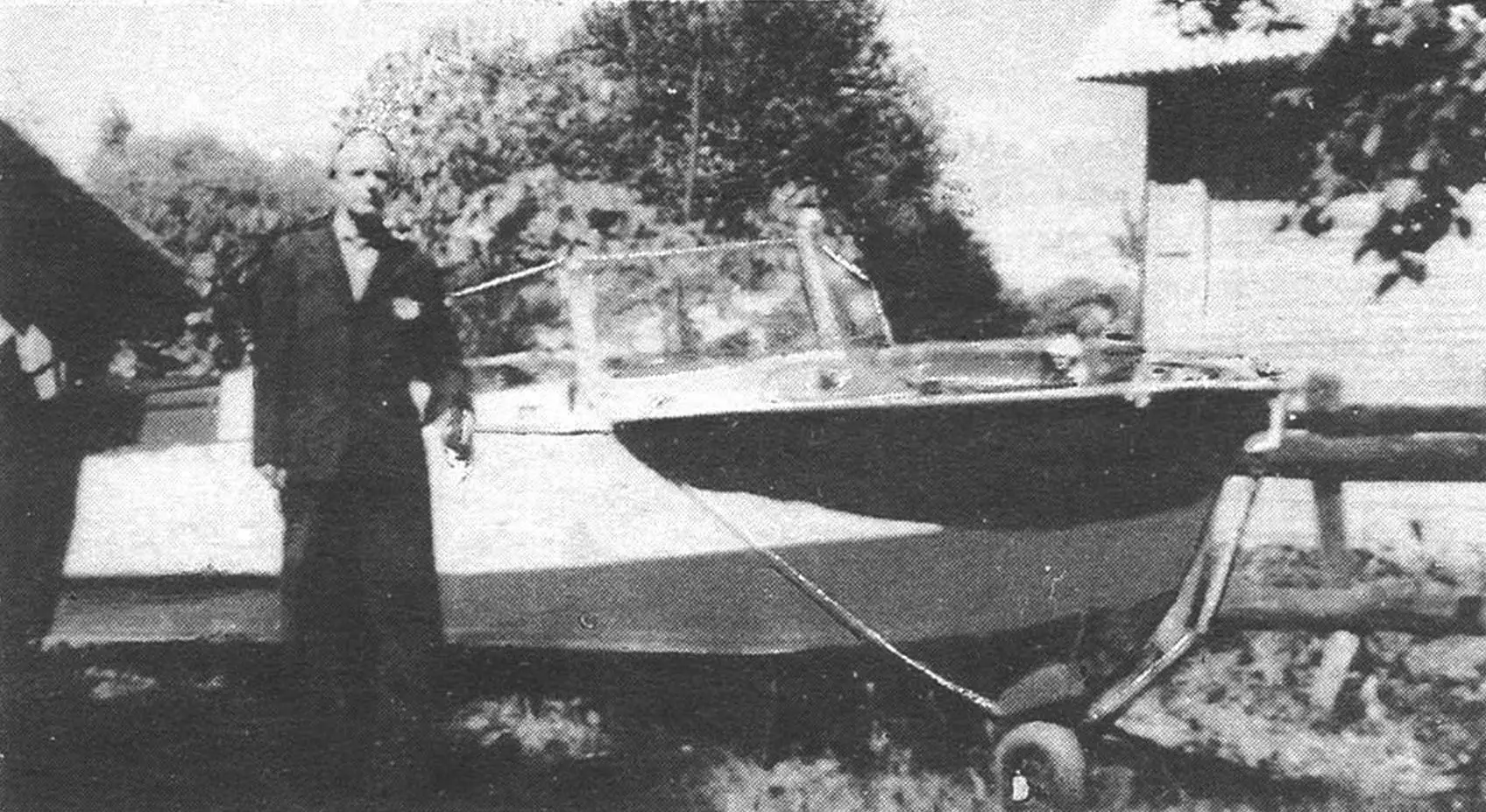
The tourist amphibious boat “Amfa” was built by Vitaly Gennadievich Lebedev 35 years ago. Over many years of operation, it naturally underwent several modernizations, but the original design ideas embedded in it have not become obsolete. “Amfa” still pleases its creator and his family, demonstrating excellent qualities both on water and on land.
In the late 1950s, when life after the war became easier and the children grew up, I wanted to show them new interesting places. We lived almost on the shore of the Moscow-Volga Canal, and water transport, as is known, is the cheapest. That’s how the idea to build a boat was born.
I set myself the task of making it a tourist boat, of an amphibious type with a simplified design, that is, without complex units and assemblies of the wheel lifting system, without unnecessary holes in the hull. In two years, I fulfilled my dream.
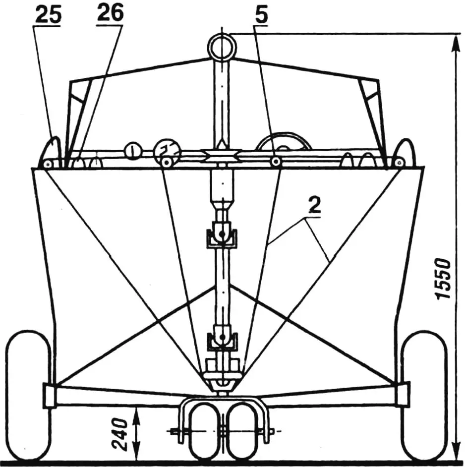
(In the top view, column pos. 24 is shown in the lowered position. Elements 11 and 16 are conventionally not shown):
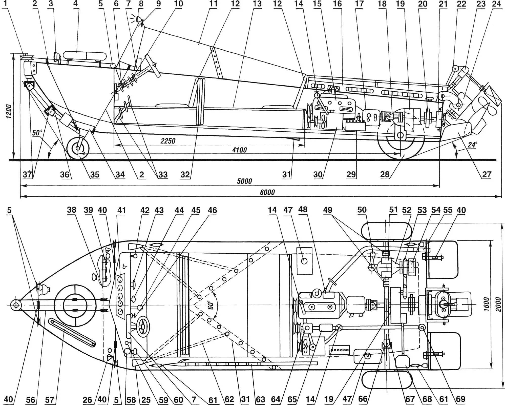
1 — bow steering drum;
2 — wheel fastening cables (steel, Ø4.5 mm);
3 — headlight;
4 — life ring;
5 — rollers;
6 — wheel control drum;
7 — instrument panel from M-20 “Pobeda” car;
8 — masthead light;
9 — rearview mirror;
10 — rudder control drum;
11 — wheelhouse glazing (plexiglass, sheet, thickness 8 mm);
12 — removable seat backs;
13 — beam (D16T alloy, 30×30 mm angle);
14 — water valves;
15 — engine;
16 — engine compartment hood;
17 — gearbox (GB);
18 — driveshaft (from GAZ-69 car);
19 — transfer case;
20 — rubber-metal coupling;
21 — bearing assembly;
22 — folding column lifting bracket;
23 — worm steering reducer;
24 — folding column;
25 — air intakes;
26 — side lights;
27 — transom plate (foam plastic);
28 — wheel 660×220 mm;
29 — battery 6ST-55;
30 — water radiator;
31 — step;
32 — wheelhouse roof in folded form (D16T sheet, thickness 1 mm);
33 — pedals;
34 — wheel turning reducer with support;
35 — front wheels (300×125 mm);
36 — driveshaft (tube 35×2.5 mm, steel 30KhGSA);
37 — universal joints;
38 — watertight bulkhead;
39 — forepeak hatch;
40 — turnbuckle;
41 — engine operation monitoring instruments;
42 — differential lock handle;
43 — carburetor choke handle;
44 — throttle position lock (“manetka”);
45 — gear shift lever;
46 — ignition switch;
47 — fuel tank (volume 22 l);
48 — exhaust manifold cooling jacket;
49 — connecting couplings;
50 — differential lock lever;
51 — wheel reducer;
52 — differential;
53 — sprocket z = 18 (from IZh-59 motorcycle);
54 — brake drum;
55 — muffler;
56 — front wheel control cable;
57 — winch cable;
58 — log (speed indicator);
59 — column lifting control toggle;
60 — column locking handle when moving in reverse;
61 — cleats (for mooring);
62 — air supply tubes to sealed space (4 pcs.);
63 — boat hook;
64 — water pump BNK-12;
65 — oil radiator;
66 — driveshaft (from SZD motorized wheelchair);
67 — connecting shaft (tube 30×7 mm, steel 30KhGSA);
68 — winch;
69 — water filter.
The hull (fig.1) with low deadrise was riveted from duralumin (D16) sheets 1.5 mm thick and 30×30 mm angles. The bottom was coated inside with epoxy resin and fiberglass and equipped with an arrow-shaped transverse step (31). It is made according to the recommendations of the “Boats and Yachts” magazine, when air is supplied from air intakes (25) located on the deck on both sides into the stepped space. Thanks to this device and transom plates (27), the average speed increased by 5 km/h, and the boat’s ride became smoother, as impacts on the bottom in heavy seas were significantly reduced.
To protect passengers from spray and rain, the boat’s wheelhouse was equipped with glazing (11) and a roof (32), which can be removed, disassembled, and stowed behind the back of the front seat if desired.
The bow compartment (forepeak), which has only a hatch (39) 450×350 mm in size in the bulkhead (38), is completely sealed. In one of our trips, such a design prevented a major disaster: returning to camp at night at a speed of about 50 km/h, we hit an unlit buoy and got a hole in the forepeak, it filled with water, but the boat with a bow trim remained afloat and we, with difficulty, but reached our bay.
The engine compartment houses the engine (15) from GAZ-21 with clutch, gearbox (17) from “Pobeda” car, homemade transfer case (19), winch (68) and other power plant and transmission units. All this is covered by an easily removable hood (16).
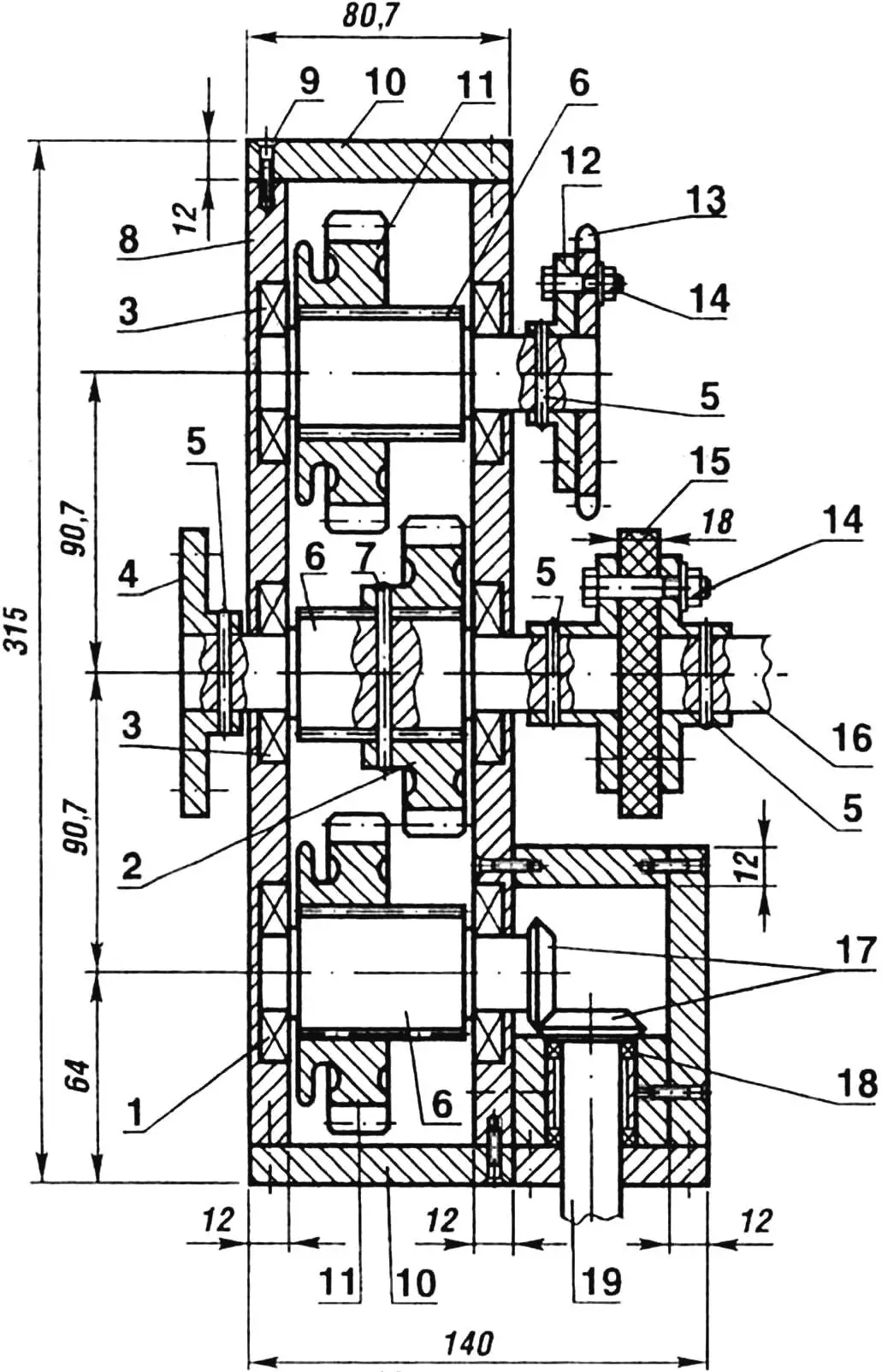
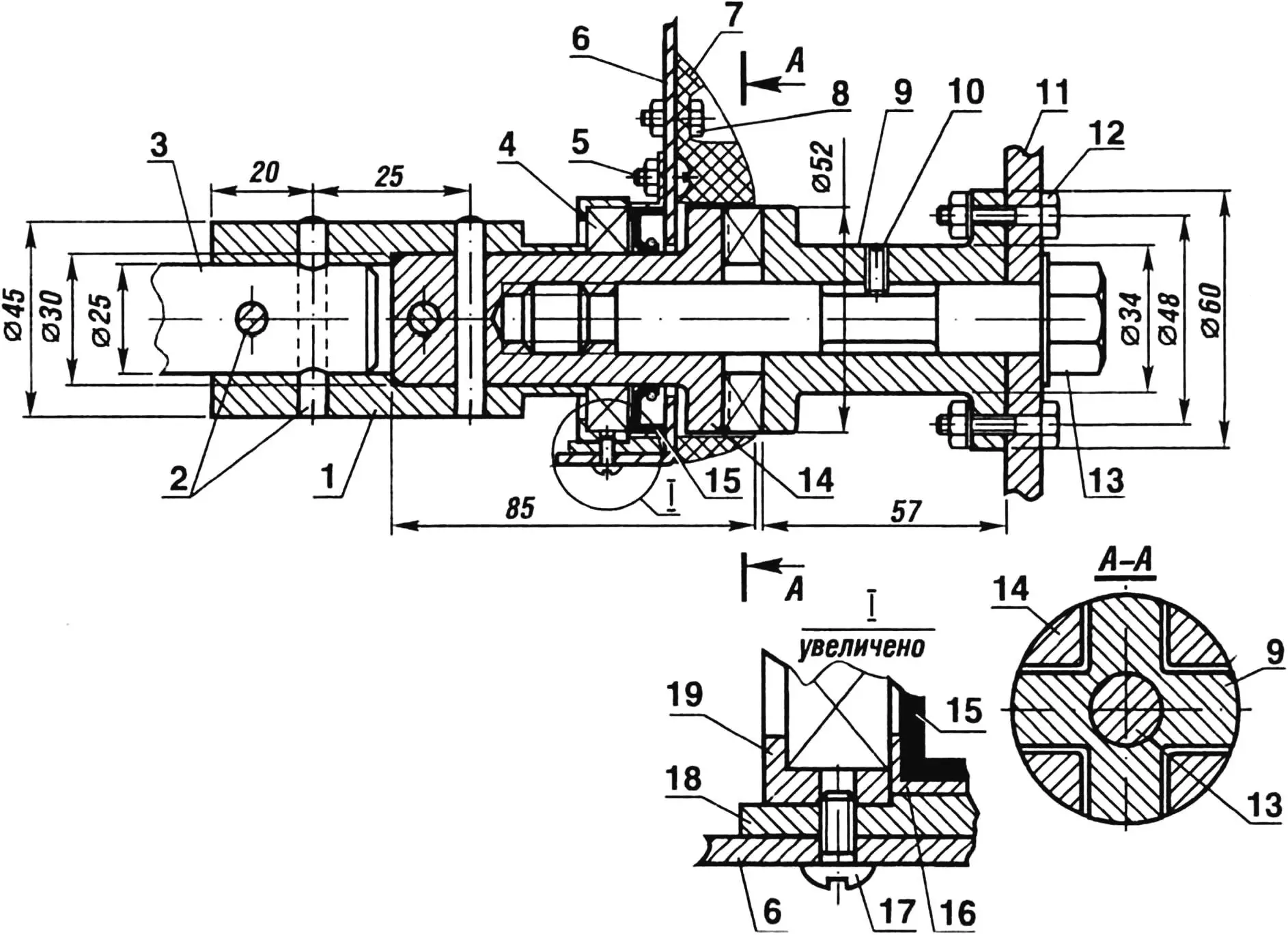
1 — bearing 7000105 (2 pcs.);
2 — gear (shortened, from M-20 GB first gear);
3 — bearing 7000106 (4 pcs.);
4 — connection flange with shaft from M-20 gearbox;
5 — pins (steel 30KhGSA, rod Ø5 mm);
6 — shafts (shortened secondary, from M-20 GB);
7 — pin (steel 30KhGSA, rod Ø6 mm);
8 — crankcase side wall (D16TV alloy);
9 — screw M6;
10 — crankcase covers (D16TV);
11 — sliding gears (from M-20 GB first gear);
12 — flange (steel 45);
13 — differential drive sprocket (z = 19, from IZh-49 motorcycle);
14 — bolts M8;
15 — rubber-metal coupling;
16 — bearing assembly shaft;
17 — bevel gears (z₁ = z₂ = 19, steel 20Kh);
18 — bearing 60202 (2 pcs.);
19 — winch drive shaft.
As for the engine, initially I installed a motorcycle engine from IZh-49 with 10 hp. I converted it for water use, but the boat’s speed with it was only 15 km/h. This situation did not suit me, and I decided to buy a 75-horsepower “Volga” engine from a consignment store. I made radiators for it: oil (65) and water (30) with a rotary pump BNK-12 (64), and welded a water cooling jacket (48) on the exhaust manifold. The pump and oil radiator fan drive is carried out by a belt drive from the engine flywheel. Tests showed that in this version, the amphibian can reach speeds on land up to 25 km/h, and on water — up to 55 km/h. The engine power is quite sufficient for towing a water skier and there is still a small reserve.
As a propulsion unit, I used a bronze three-blade propeller (outer diameter 440 mm), installed on a folding angular column. The torque transmission to it from the drive shaft is by means of a detachable cam coupling and a reducer built into the column housing, consisting of two bevel gear drives (i1=0.55, i2=1). For the first, gears from the rear axle of GAZ-51 car (half-shaft z1=20 and satellite z2=11) were used, and for the second — a pair of gears (z3=z4=17), made from 12KhN3A steel and case-hardened. Moreover, the first (upper) pair is bathed in oil, cooled by seawater passed through a coil built into the column crankcase. The column reducer is non-reversible, so on water, forward and reverse GB gears are used. When moving in reverse, to prevent the column from tilting upward, it is locked with a special latch. The control handle for the locking mechanism is brought to the driver’s station.
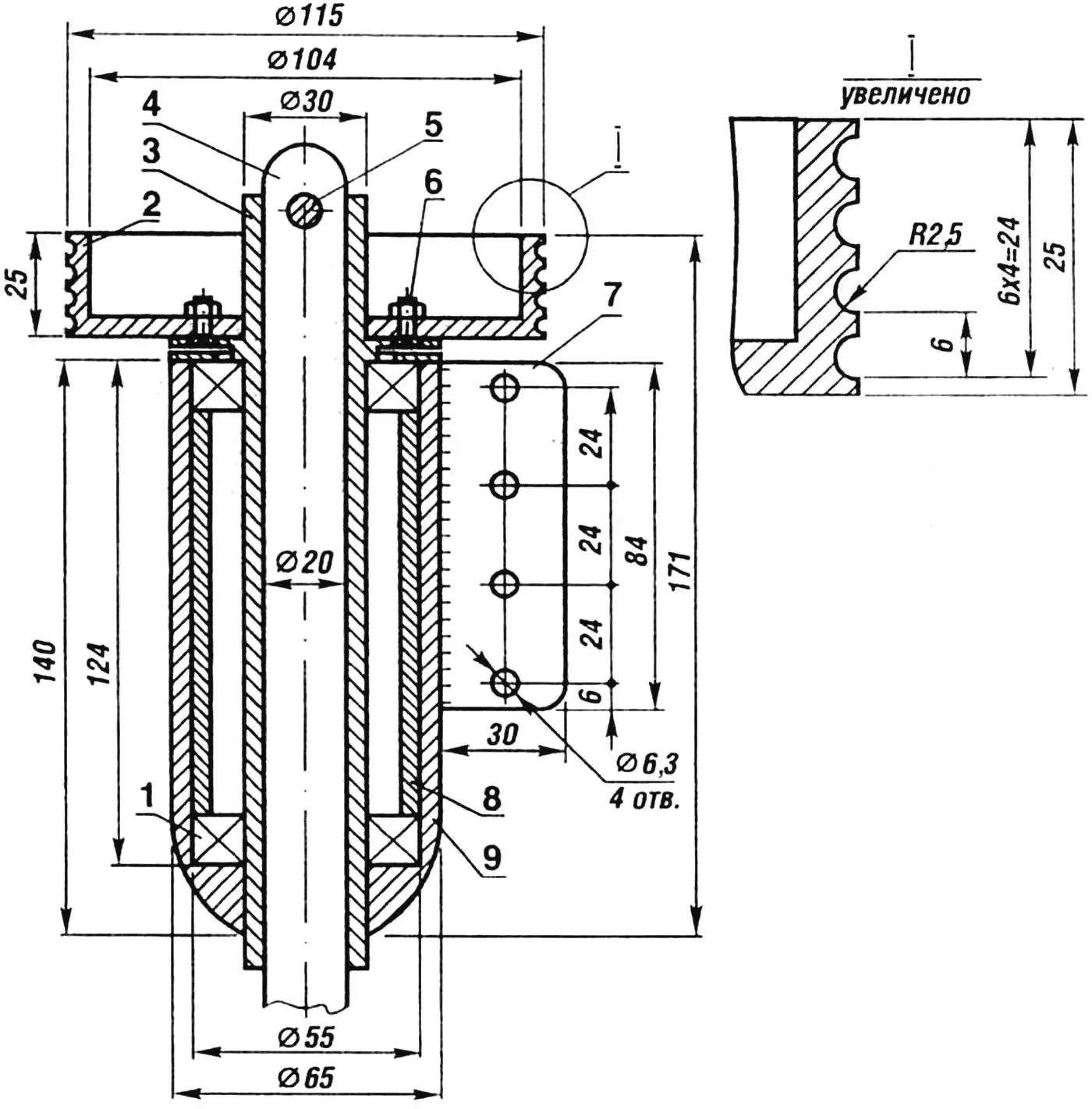
1 — bearing 7000106;
2 — drum (D16T alloy);
3 — drum shaft (steel 30KhGSA);
4 — driveshaft, upper section (steel 30KhGSA);
5 — bolt M8;
6 — screw M6;
7 — mounting cheek (steel 20, sheet thickness 2 mm, 2 pcs.);
8 — spacer bushing (D16T);
9 — housing (steel 45).
The rudder is actuated by cables laid along the sides between two drums (on the steering column and behind the transom board), and further by a transmission consisting of a horizontal shaft with a detachable cam coupling, a worm reducer, and a vertical shaft.
Raising and lowering of the angular column is carried out by an electric motor (MA-40A) with a worm-gear reducer and a drum for winding the cable, fixed at the other end to the steering mechanism reducer housing (23) and passed over the lifting bracket block (22).
1 — connecting coupling (steel 30KhGSA);
2 — pins (steel 45, rod Ø8 mm);
3 — connecting shaft (steel 30KhGSA);
4 — bearing 7000106;
5 — screw M5 for mounting seal housing;
6 — boat skin;
7 — fairing (foam plastic);
8 — fairing mounting bolt M6;
9 — adapter (steel KhVG);
10 — limiter (screw M6);
11 — wheel disk (D16TV alloy);
12 — bolt M8;
13 — special wheel mounting bolt M16×2 (steel 30KhGSA);
14 — half-shaft (steel KhVG);
15 — seal 1-30×52-3;
16 — seal housing (steel St3);
17 — set screw M5;
18 — spacer (D16T);
19 — bearing housing (steel St3).
The chassis is made according to a three-wheel scheme: the front wheel is steerable, the rear ones are drive. All wheels are easily removed and installed on water, with the front one — together with the control system (driveshaft). To mount the front wheel, from the deck, the upper section driveshaft is inserted into the bow steering drum and secured with a bolt. Then the wheel with a support, made in the form of a cradle and serving simultaneously as the housing of the turning bevel reducer, is brought under the amphibian’s keel, “like on reins,” with the help of four cable stays (2). The latter have turnbuckles (40), with which the support is reliably pulled to the bottom. The rear wheel together with the adapter is attached to the half-shaft with one bolt (fig. 2).
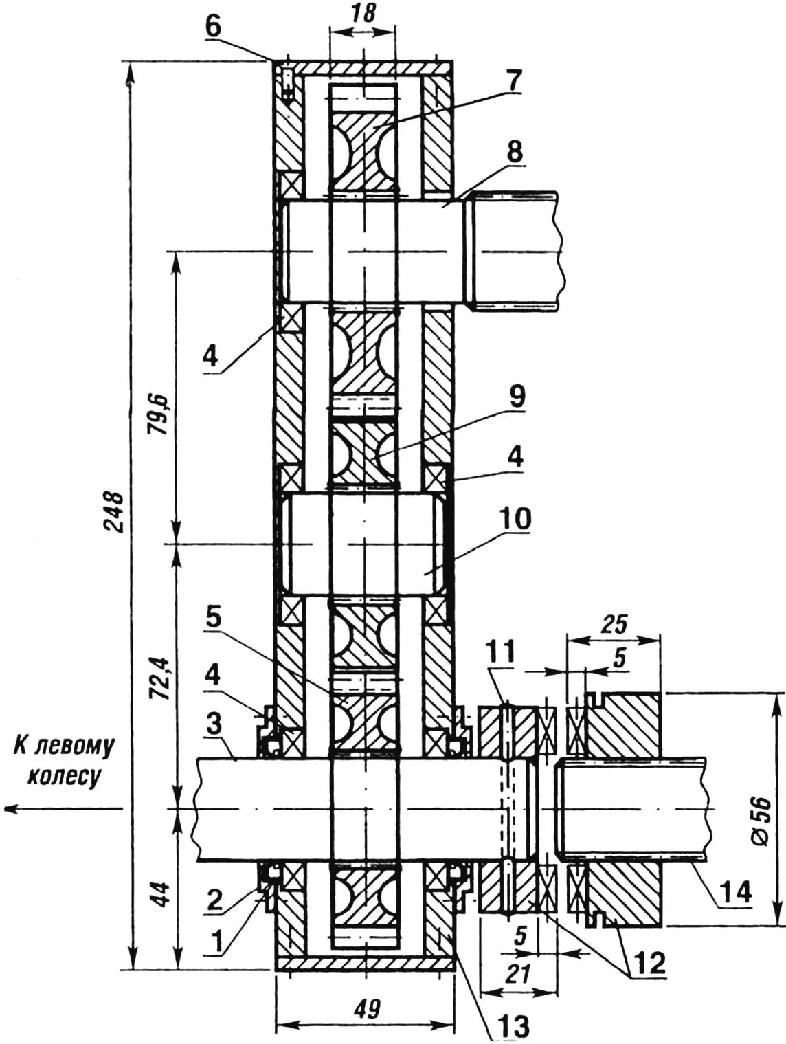
1 — seal 1-25×42-3 (2 pcs.);
2 — seal housing (D16TV alloy);
3 — output shaft (steel 30KhGSA);
4 — bearing 7000105 (5 pcs.);
5 — gear z = 18 (reverse, from GAZ-51 GB);
6 — screw M6;
7 — gear z = 22;
8 — differential half-shaft;
9 — gear z = 22;
10 — intermediate shaft (steel 30KhGSA);
11 — pin (steel 45, rod Ø8 mm);
12 — differential lock coupling (from SZD motorized wheelchair final drive);
13 — reducer crankcase (D16TV alloy);
14 — left wheel connecting shaft.
The torque from the engine is transmitted through the GB by a driveshaft from GAZ-69 (fig.1, pos. 18) to the transfer case, which divides the transmission into three branches: to the propeller, drive wheels, and winch. The last two branches can be engaged simultaneously. Transmission to the propeller is carried out directly through a rubber-metal coupling (20), to the second branch — by chain drive, through the differential (52) and wheel reducers (placed together with the differential in one sealed housing made of sheet metal), connecting driveshaft (67), half-shafts, and splined couplings. Wheel reducers with a small gear ratio (i=0.83) serve to increase ground clearance and to apply differential lock, which facilitates the amphibian’s exit from water onto a gentle shore. When moving on land, braking is performed by a brake drum from K-125 motorcycle, which is attached to the differential flange.
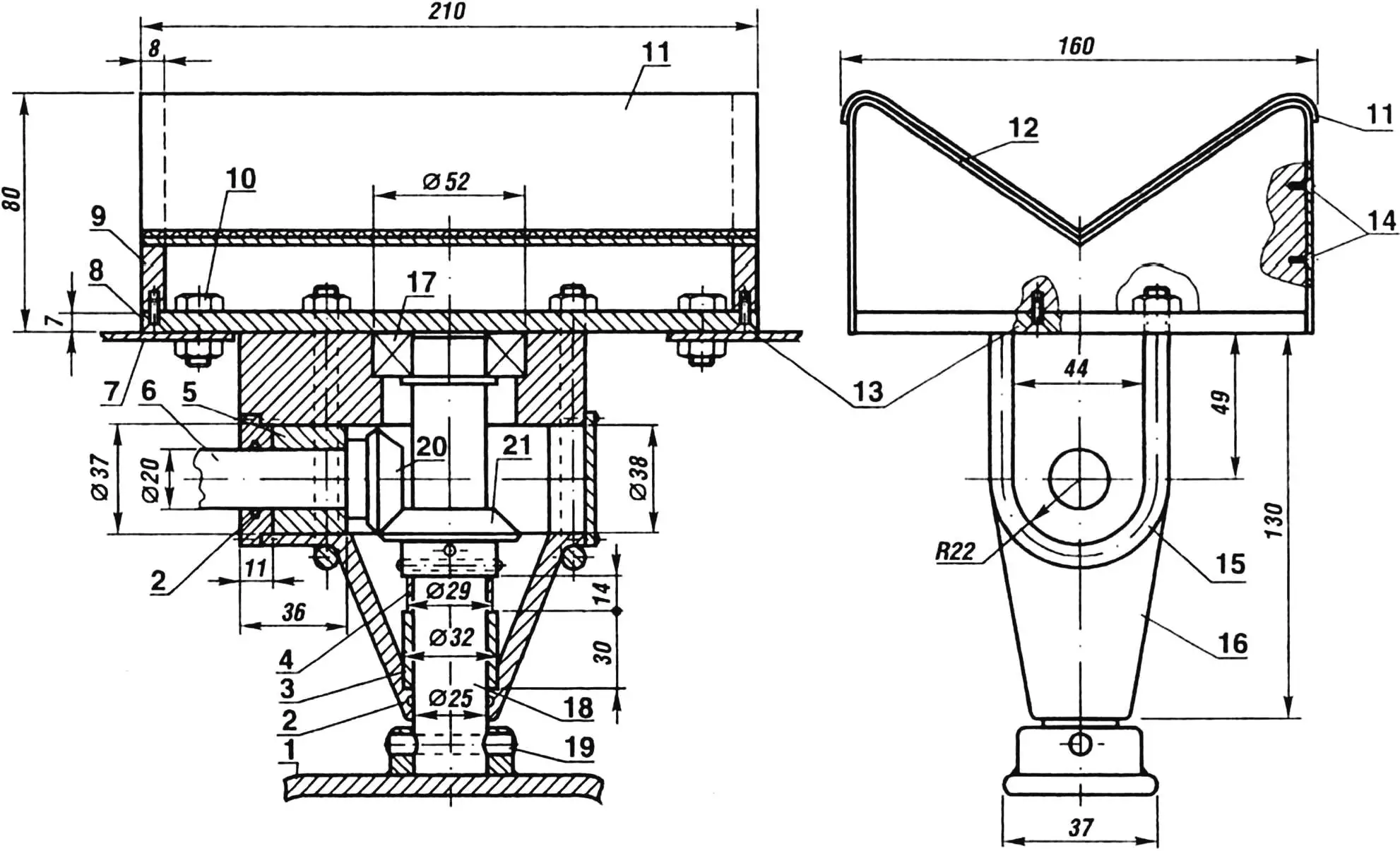
1 — fork (steel 45);
2 — seals;
3 — bushing (bronze BrS30);
4 — bushing (steel 45);
5 — bushing (bronze BrS30);
6 — driveshaft, lower section (steel 30KhGSA);
7 — wheel fastening cable (Ø4.5 mm);
8 — cradle base (D16T, sheet, thickness 7 mm);
9 — cradle posts (D16T, 2 pcs.);
10 — cable mounting bolt M8;
11 — covering (rubber, sheet, thickness 2 mm);
12 — skin (D16T, sheet, thickness 2 mm);
13 — screws M5;
14 — screws M4;
15 — stirrup (steel 30, rod Ø8 mm);
16 — reducer housing (D16T alloy);
17 — bearing 7205;
18 — shaft (steel 30KhGSA);
19 — pin (steel 45, rod Ø10 mm);
20 — bevel gear z = 16 (steel 20Kh);
21 — bevel gear z = 28 (steel 20Kh).
Before the amphibian goes ashore, the wheels are installed, the column and transom plates are raised, a muffler sleeve is inserted into the exhaust pipe, water valves are switched, and a belt is put on the radiator fan. If the exit is gentle and the wheels have touched the bottom — the differential lock is engaged. In case of difficult exit, a winch cable is secured on the shore, which creates an additional force of 1 ton.
“Amfa” was operated for more than one decade. Many trips were made on it along the Volga and its tributaries. And how much joy water skiing brought! The amphibian’s design, including the folding column, fully justified itself. During all this time, the propeller was never damaged, although we ran aground many times. You won’t believe it — “Amfa” still looks like new.
V. LEBEDEV
Recommend to read
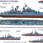 GIVEN COMBAT EXPERIENCE
The lessons of the Second world war, naval warfare was not quite obvious and understood immediately. The first attempts of consideration of combat experience led to the emergence of the...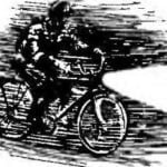 BRIGHTER AND SMOOTHER
Industries is not only "pedal" means of transportation and sports equipment to strengthen leg muscles. In the right hands it is easily converted into a variety of small-scale...
