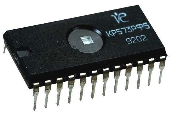
 Debugging any program of the microprocessor, it is necessary many times to write and erase information in the chips ROM КР573РФ5 (РФ5). However, the online those is very limited. In the end — quick exit of the chips from the system.
To reduce the consumption РФ5 makes use of the RAM chips КР537РУ10 (РУ10) as emulator ROM. Among studies of the feasibility of the proposal and the fact that both chips are almost identical on the “Pinout”. The discrepancy between some of the digits of the number addresses conclusions special role in this situation does not play, because it only determines the location information inside the chip. As a rule, to work as part of the equipment is sufficient to under ‘ was assigned the same group of conclusions.
Of course, it should take into account the specifics of such chips. In particular, the limitations associated with the risk of Erasure of information when de-energizing the RAM chips. But the consumption of electricity in her mode of data storage is small (especially at reduced supply voltage), and charge the “regular” 2200-microfarad capacitor is sufficient to hold the electronic memory in an unaltered state for about an hour. It is encouraging that for transferring the chip from the programmer to the target block or back is enough even a few seconds.
Of course, the supply of nutrition necessary for the functionality of the chip in case of accidental touch to her findings, significantly accelerates the process of discharge of the capacitor. From the point of view of operators, the greater the capacity and the lower the leakage current of the capacitor, the better.
To write information to the chip RAM in any programmer designed for entering data into a ROM chip. You can just use the offer of a homemade device. Its peculiarity is that the programmer during writing needs to access the chip even when written in the memory cell information — FF.
There are programmers who just miss the cell with such information. Their use in a homemade device is not desirable. The fact that the cells will remain incidental information arising during supplying power to the chip RAM.
Homemade device works so that the write signal intended for feeding on vyv. 18 РФ5, is inverted by the transistor VT2 and served on printin.21 records РУ10. Transistor UT1 — blocking. It completely eliminates the false record of information while reading, when printin.20 chips served РФ5 log.0.
Signal read, coming to conclusions.20 РУ10, the same as on the conclusions. 18 РФ5.
Chip РУ10 constantly selected alarm log.0 at its output 18. The capacitor C2 is connected to +5 V through the diode VD1, whereby on printin.24 РУ10 maintained the required voltage even hours after the power is turned off (completion of programming).

Electrical schematic of a homemade device, allowing the use of chip КР537РУ10 as emulator ROM КР537РФ5
After recording the information in the chip RAM РУ10 disconnected and transferred (together with soldered thereto a resistor and a capacitor C2) to a custom block in the on state. This is not to touch bare wires or pins of the chip, not to lower the supply voltage.
Structurally, the device is a personal unit, if it is used by programmer to connect their conclusions and each specific “flash” the chip or console http://www.inetkomp.ru/uroki/631-podklyuchit-monitor-k-kompyuteru.html. The latter is connected to the programmer instead of the chip. And the same connector, which include РФ5.
The device can be assembled on РФ5 as faulty on the Board. For this the chip must be drilled in the center to remove the crystal to separate its conclusions. Then the findings must be soldered to a radio in accordance with the concept of the device and the socket to install РУ10.
You can solder to the power pins of the chip, the additional condenser of small capacity (on the circuit diagram it is not shown), using it as a handle. The connection of such a capacitor is in parallel with the main recording, which is connected to a long flexible wire with a chip to have the possibility of easy installation in equipment. The chip needs to be soldered on the resistor, misleading КР537РУ10 mode storage of data during its carrying.
SOLONIN, Konotop, Ukraine


