
 You see on TV the most interesting hockey meeting. The team played brilliantly, passions are running high. At that moment in the opponent enters the washer. You even consider not managed properly, as it happened. That’s a shame!.. But this time on the TV screen in slow motion again there are the same exciting footage.
Wondering whether you ever how is this happening? One thing is clear: the game at the same time with television coverage on tape, which can then be read again. Videos are stored indefinitely and can be broadcast as needed. And how do this article.
Attending sporting events or sitting in a concert hall, you probably noticed time and again the television cameras, leading transmission directly into the air. They are the first stage of the video.
Now for this purpose there are used a magnetic recording system, and relevant devices called VCRs. They work on the same principle as conventional tape recorders: the converted video signal is supplied to the magnetic heads that write to tape. The main difficulty lies in the need to record and playback a broad band of frequencies from 50 Hz to 6 MHz, corresponding to modern television standard (audio — 20 Hz to 20 kHz).
The signal frequency of 6 MHz can be recording, if the tape speed is 30-40 m/s. In this case, the wavelength of the record, the corresponding low-frequency oscillations, will be about 0.5 m. Therefore, to reproduce them using the heads from the normal of the tape impossible. Frequency distortion in a direct recording of signals in the range of 50 Hz to 6 MHz is huge, and their correction is not feasible due to the simultaneously occurring phase distortions. So in the video produce frequency modulation of the auxiliary signal to the video signal, and as a result its spectrum is shifted to the high frequencies. The thus obtained frequency-modulated signal is recorded on tape. Thus the difficulty of reproduction of low-frequency components are eliminated. When playing FM signal demodulator.
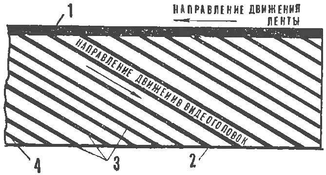
Fig. 1. Layout of tracks on a magnetic tape with oblique-lowercase entry:
1 — track, 2 — support tap strips, 3 — track recording of the video signal, a 4 — track recording capability.
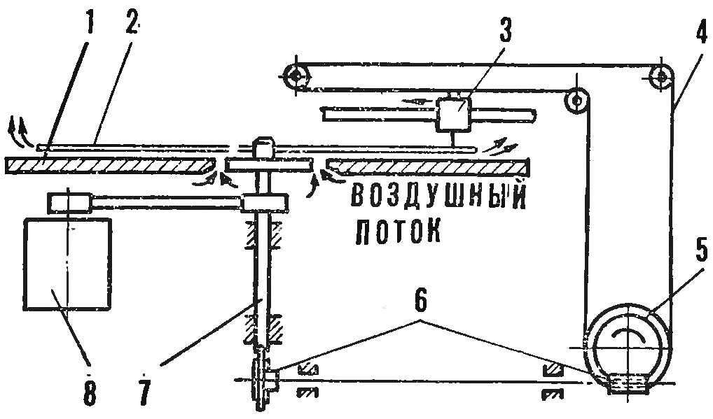
Fig. 2. Kinematic diagram of the video player with a diamond needle:
1 — support plate, 2 — DVD, 3 — adapter, 4 — wire, 5 — reel, 6 — transverse transmission, 7 — shaft, 8 — motor
To moderate the speed of the magnetic tape writing speed was high, used a slanted-line method of recording using a rotating magnetic head block. Usually the picture and sound are recorded on the same tape (sound — longitudinally, at the edge of the tape, Fig. 1).
The most common chetyrehrjadnye VCRs. Entry signals doing in the tape width 50.8 mm moving at a speed of 39.7 cm/s, block of four heads rotating at a speed of 15 000 rpm Speed recording and playback amounts to 41.4 m/s. three-Engine tape drive mechanism of such a tape recorder has a complex system of automatic gain control speed.
Today video is used in scientific researches and in educational process. However, possibilities are not limited only to the professional framework. Industry produces household portable video recorder “electronica-501-video”, intended for recording television images of the European standard (50 Hz, 625 lines) and sound from the TV camera “electronics-video” or TV with a matching unit. Moreover, the record is reproduced on a television receiver.
Currently, work is underway on creating a system for video playback at home on a qualitatively new principles. Here we are talking not about magnetic recording, and about creating a video with a set of DVDs that can be played like a normal record. This idea is attractive for its simplicity. You buy a DVD with any of your favorite cartoon or recording of the famous artist, bring home and put on the video. Latest clips through the antenna connected to the TV, the screen which will display the image from the DVD. So, over time you’ll make up your own video library, like the library or the music library.
A system of video playback occurs simultaneously in three different directions. We note immediately: the similarity of DVDs with the usual record purely superficial. By modern standards, high quality recording meet
300 000 information bits (ones capacity of information) per second at a density of about 5000 bits per mm2. That is the usual plate with a speed of 33 1/3 Rev/min is calculated on the program in 30-40 minutes And when recording television images, the information flow becomes 100 times harder and denser, although the surface area of the disk will remain the same.
The first version of the video looks like normal electrophone. Applying a frequency-modulated carrier oscillations, the disc is cut a groove on which is recorded the full range of video and audio signals. The reduction of the distance between the grooves to a minimum allows you to increase the number of radial paths from 14 to 140 mm, and this, in turn, increases the density of the recorded information 100 times. The pickup is a sharp diamond needle rigidly attached to the piezoelectric element. It converts vibrations of the needle into electrical signals(Fig. 2). Color television image is recorded so that for each frame there was one full revolution of the disk. Then, when the TV standard 25 frames per second, the disk must rotate at a speed of 1500 rpm (recording played for 10 min). The disc is easily damaged, so remove it from the package and puts it back after playing a special machine.
The second version of the video (it is developed by the Dutch firm “Phillips”) is based on phase modulation of laser beam in the role of the non-contact optical pickup (Fig. 3). In the process of recording with a laser cut disk oblong recesses with a width of 0.7 microns and a length from 0.8 to 2.5 microns, successive continuous spirals. Due to the extremely small size and high density of the recesses are located at a distance of two microns from each other — for phase modulation stack up to 500 tracks per radial mm. This unilateral phase-modulation drive is designed for 30-minute program that consists of three layers: protective, informative and highly reflective layer of aluminum.
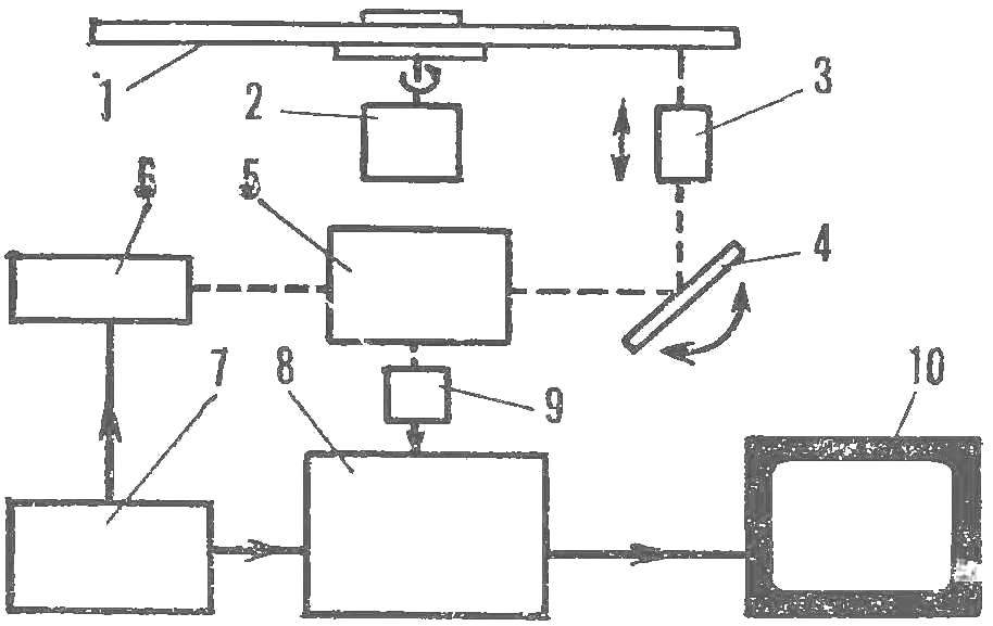
Fig. 3. A block diagram of a laser video:
1 — DVD, 2 — motor, 3 — lens, 4 mirror, 5 optical system, 6 — laser, 7 — power, 8 — camera, 9 is a light — sensitive device 10 a TV.
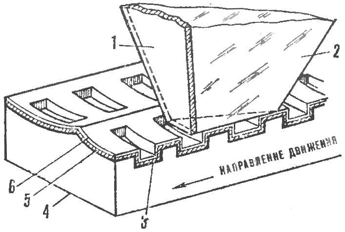
Fig. 4. The structure of a capacitive disc video player:
1 — metal, 2 — sapphire needle, 3 — metal pad, 4 — vinyl, 5 — styrene, 6 oil.
Beam helium-neon laser power of 1 mW focused to a point Ø 1 MC on the DVD. Reflected from the aluminum layer through a focusing lens it is directed to the photodetector. The latter converts the light signal into electrical “image — sound”. Thus, the light-heat running on the track of the rotating disc, crossing containing video information of the recess. The reflected light beam is modulated depending on you-cell and length. And because there is no needle cartridge and thus mechanical contact with the disc, the latter may be very long.
Capacitive video occupies an intermediate position between these two devices. As in the first, it uses a disk coated with it grooves, which reads the mechanical pickup. The track is located at a distance of 4.57 MK from each other, with a density of 225 per radial mm. The disc consists of five layers (Fig. 4). Vinyl contains the core information gap length from 0.23 to 1.23 MK. On both sides is a layer of metal and styrene coating. Styrene is applied over the layer of oil that increases the longevity of both the disc and the pickup needle. Double-sided discs designed for shestidesyatigradusnuyu program.
The signal recorded on the disk, reproduces the capacitive sensor. A thin metal coating on the end of a sapphire needle of the cartridge serves as one electrode, and the metal layer in the disk, the second plate of the capacitor. Styrene coating acts as a dielectric When the needle moves along the groove through the information cracks, the stress changes between the capacitor Plates is transferred to a special unit in which there is the strengthening and transformation of written information into a standard video signal.
Unlike systems with a playback speed drives 1500 rpm, mechanical-capacitive system is designed to speed 375 rpm This corresponds to the passage of four frames per revolution of the video disc. The relatively slow speed of playing, together with the use of a simple mechanical cartridge significantly reduces the cost of such videoprogramma devices. With careful handling the disk can withstand not less than 100 playbacks, and the durability of the needle of the pickup — approximately 200 hours of continuous operation.
The video, which we now are told, are under development. Some of them will be more successful — time will tell.
L. MOROZOVA
