 People even slightly familiar with the device of the internal combustion engine, knows everything that could improve it is improved, what can be changed — changed, requiring modernisation — modernised. And yet there are designers, including Amateur that can’t live without having to constantly improving the heart of any transport vehicles — the engine.
Lives in Moscow, a restless man — Abramov Alexander Sergeevich. Fourteen-year-old boy he first became acquainted with engines in the automotive workshop ilina, worked in Moscow, Karetny Ryad. It was in 1909. In the first world war he served as a mechanic in the division’s armored vehicles. Engines at that time had a lot of problems with drivers. So I had Sasha to learn the “wisdom” of the repair and maintenance of these still imperfect and Moody motors. Since then Abrams and “sick” the invention. The years went by, and a passion for improving, for creating the original engines did not pass. In 1926, Alexander builds his first car with an engine of his own design. The crowd of passers-by and policemen enchanted looking, unusual car. At that time, not so much in Moscow of cars, and this is very very unusual — homemade. It was the original nodes: friction stepless gearbox, drum brake, acting directly on the tyre of the wheel, and original from start to finish made with their own hands the engine.
Not going to count how many inventions and discoveries in various fields of technology did Alexander Sergeevich (this might be a topic for another story), but during his long life (he’s now 83), he managed to invent and build almost a few dozen unusual engines. Some of them performed only in the plastic working models, others embodied in the metal and sat in on a test stand, and still others have served on microvesicle and cars which Alexander had built with the guys in technical circles at stations of young technicians and yard design office at the Hoo.
Today we introduce our readers with some diagrams of engines, tested by Alexander Sergeyevich and active in his home laboratory.
Rotary VANE ENGINEshown in figure 1, powered by compressed gas. Its main advantage over other machines volumetric type, is the lack of the translational moving parts. For smoothness of operation it is comparable with electric motor and can be used to rotate a small hand drill. The main parts that comprise the engine, a cylindrical rotor, with two spring-loaded plates, ensures sealing of the working chambers, and a stator having a cylindrical shape. The greater the eccentricity of the rotor, the more torque the engine develops, but his work is deteriorating at high speed.

Fig. 1. Diagram of a rotary vane engine:
1 — stator, 2 — folding plate-damper, 3 seal, 4 — rotor
The CAM-PISTON ENGINE with rotating cylinders rotative, whose scheme is shown in figure 2, also works ka compressed gas. It works in the following way. In each cylinder there is a piston-based bottom part through the roller on the Cam, fixedly mounted on the frame of the motor. In the body of the cylinder drilled the air channel, one side facing newportnews space, and the other is connected to the spool mechanism vozduhorazdelenija manifold. To preserve the correct kinematics of the pistons, which can be broken from the action of centrifugal forces during rotation of the cylinder around its axis, the pistons pulled together to the center ring by a spring mounted on the elongated axes of the rollers.

Fig. 2. Scheme of the Cam-piston engine with rotating cylinders:
1 — cylinder, 2 — piston, 3 — Cam, 4 — roller, 5 — rotating the base cylinder, 6 — inlet, 7 — spring, 8 — spool mechanism.
The joint work of the slide mechanism and the Cam that provides the movement of the pistons, agree (sinhroniziruete) commencement of injection of compressed gas with the time of movement of the piston from top dead center to the bottom. At the end of the working stroke of the air channel through the slide valve device is connected with a cavity communicating with the atmosphere.
The power comes from the chain sprocket or gear mounted on the cylinder block, and simultaneously performs the role of a flywheel.
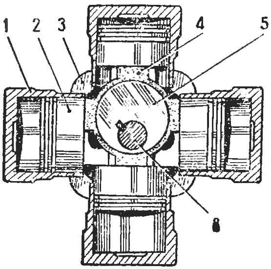
ECCENTRIC-connecting rod free PISTON ENGINE is also a gas. In two mutually perpendicular cylinders are pistons, connected in pairs by connecting strips. The axis of rotation of the eccentric that moves the pistons is located at the intersection of the longitudinal axes of symmetry of the cylinder. For one full rotation of the shaft, each piston makes a complete working cycle for a given kinematic scheme corresponds to the four working strokes. This ensures the smooth running of the engine. Naturally motor the same as considered in the previous scheme.

Fig. 3. The scheme of the eccentric-connecting rod free piston engine:
1 — cylinder, 2 — piston, 3 — Carter, 4 — pusher, 5 — Cam, 6 — PTO shaft 7 — and the heel (steel).
Young designers can try their hand and to make in school, at the station of young technicians, or in the Palace of pioneers engine for one of these schemes. It is not necessary to do all the details themselves.
You can use plastic (polystyrene, Styrofoam) pencil cases or boxes of cylindrical shape, for example, from the pills.

